By J. A. "Sam" Wilson, CET.
-------
Your comments or questions are welcome. Please give us permission to quote from your letters. Write to Sam at:
J.A. "Sam" Wilson c/o Electronic Servicing P.O. Box 12901 Overland Park, Kansas 66212
------
This Technical Notebook describes an experiment that any technician can perform. The results will prove an important point about the dielectric in a capacitor.
Making an electret
A permanent source of electric flux can be produced easily. It is called an electret, and it is constructed by these steps:
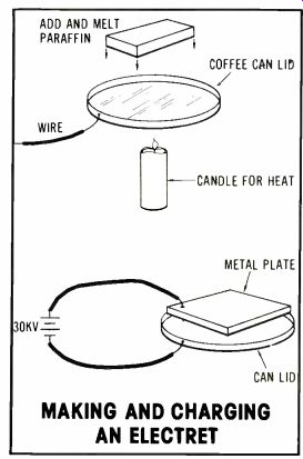
Attach an insulated wire to a metal coffee can lid, as shown in Figure 1.
Spray the inside with a non-stick coating such as used in frying pans. The reason is given later.
Melt some paraffin in the lid, filling it to the brim. A large candle can furnish the heat.
Prepare a flat piece of metal of smaller diameter than the lid (to avoid arcs) and attach a length of insulated wire.
After the paraffin is melted, remove the heat source.
Connect a source of about 30kVdc (perhaps from a TV set) to the can lid and the other piece of metal.
Taking care to avoid arcs and shocks, hold the metal so it barely touches the top of the paraffin as it hardens. Remember: the 30kV must be in contact with the paraffin until it is solid. (See Figure 1B.)
Disconnect the high voltage.
Remove the top plate (again using precautions against shock). Then remove the paraffin from the can lid; the non-stick coating makes removal easier.
That piece of paraffin now is an electret, which is a permanent source of electric flux in the same way a permanent magnet is a source of magnetic flux.
Electrets have several important uses, and some will be explained in a later issue.

Figure 1---An electret can be made in just a few steps. Paraffin is melted
(A), and while it cools (B), a voltage is connected. After the finished electret
is removed, it retains an electric flux. MAKING AND CHARGING AN ELECTRET

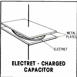
Figure 2---When an electret is placed between metal plates, it becomes a
charged capacitor.
Charged capacitor
For the next step, place the electret (charged paraffin) between two metal plates (Figure 2). The assembly is a charged capacitor! That is a very important statement because a charged capacitor has been created without any charge having been placed on the plates. After the experiment with the pails (a capacitor was formed from two metal and one insulator pails), several readers disagreed with the explanation. Their contention was that the voltage (which remains in a capacitor after the charging voltage is removed) is produced by an excess of electrons on one plate and a deficiency of electrons at the other plate.
In this experiment, a charged dielectric was installed between two metal plates. Thus a charged capacitor was formed. Obviously, no electrons were moved when the electret was changed to a charged capacitor.
It is not necessary for electric charges (such as electrons) to be moved into and out of capacitor to charge or discharge it.
Instead, a capacitor is charged when the electric field between the plates causes the dipoles in the dielectric to become oriented. The previous electret experiment would not work properly if the charging was accomplished by charge carriers on the plate surfaces.
Wire capacitor
Earlier in the series, a capacitor made of a solid piece of wire was proposed. It was based on the capacitance formula:
c ,kxNxA d
When the numerator was made to equal the value 1 (k x N x A =1), and the denominator equal to 1/1,000,000,000,000,000 centimeter, the mathematical result is a capacitor of 1,000,000,000,000,000 farads! A few readers stated the denominator should be d2. Not so. The equation is correct as written.
Several humorous letters suggested applications such as integrated circuit capacitors and energy storage for solar cells.
Some perceptive readers recognized the major weakness of the wire capacitor. Such very close spacing would cause excessive leak age, and the voltage rating would be so low that the capacitor would be useless.
Solve these problems and you can start a profitable capacitor business.
More questions
Readers continue to ask questions about operation of the dielectric in a capacitor. They ask, "If the dielectric determines a capacitor's charge, how can a capacitor with a vacuum dielectric ever become charged?"
Also, some readers insist that I stated there is no excess of electrons on one plate and a deficiency on the other.
These are the important statements:
A capacitor made with a vacuum dielectric can be charged, but it will not store energy.
Energy is stored in the dielectric of a capacitor, while the charges stay on the capacitor plates.
When a capacitor is charged, there is an excess of electrons on one plate and a deficiency on the other.
Nothing contrary has been stated in this series.
Ring counter
One reader asks for the schema tic of a free-running ring counter made with neon lamps. If another reader can help, please send the schematic in care of the editor.
Innovative experiments
Students of electronics laboratory courses need to have the work made interesting for them at times.
When I taught university-level electronics, I gave the students several opportunities to design their own circuits. They were urged to be innovative, so they were told what was to be accomplished but not how to do it. Although I as teacher had a clear idea about how the problem could be solved, I often was surprised by the unique (and often more simple) solutions.
Energy control-In an advanced class about control circuitry, the assignment was to design a circuit that automatically would reduce house temperature at night and restore the usual temperature by day.
It was expected that the students would use their knowledge of control principles and digital circuitry to solve the problem by devising an elaborate electronic circuit. Most groups did take that approach, but one lazy group chose a non-digital solution.
A shelf that could be adjusted for height was placed below the wall-mounted thermostat. On the shelf was a socket and conventional 15-W light bulb with a shade to direct the warm air upward toward the thermostat while minimizing the visible light. A 24-hour timer was plugged into a duplex power outlet and adjusted to turn on the bulb during the night hours.
Heat from the bulb raised the temperature at the thermostat and fooled it into acting as though the whole room was warmer. Therefore, the thermostat allowed the furnace to operate less often, reducing the home temperature all night. During the daylight hours, the timer turned off the bulb, and the home temperature was restored to normal.
The system worked very well after a few preliminary adjustments of the bulb height to obtain the desired temperature differential.
Other innovative experiments will be given next month.
Water in light bulb?
After the story in the January issue about students who amazed the teacher with the light bulb that operated normally although water was inside, a letter was received from reader John T. Bailey. He doubted the technical accuracy of the story. Excerpts are given from that letter.
John's first job was to conduct visitors through the Westinghouse plant so they could watch lamp bulbs being manufactured. "For a general-purpose lamp, the lead wires were sealed by fusing the glass stem around the Dumet wires.
Then the stem was fused by gas flames to the bulb and leaving a tip for exhausting the air by blowing in an inert gas after which the tip was sealed off by fusion. Next, the base (brass in those days) was cemented to the bulb with a bakelite cement, and the wires were soldered to the base. Now, for the part I don't understand. It is beyond me how a needle worked in between the glass and the metal base could let any water into the bulb....the stem press where the wires are sealed is well within the bulb and thus out of reach of a needle. I'm beginning to believe the water did come in through the wires!" While all readers are concentrating on this mystery, I will try to get water into at least one of the gross of light bulbs I purchased.
Also see: Sam Wilson's Technical Notebook--May 1979