By Forest Belt, CET
One measure of a maintenance technician comes when a breakdown occurs: How long till production is rolling again? Here are some guidelines that speed repair.
Logical troubleshooting suits all fields of electronic servicing. Con sumer technicians have, for years, used the principles of step-by-step diagnosis called 1-2-3-4 Servicing.
The concept was formalized in several books. Electronics instructors often teach this approach. It proves sensible to remember and to follow, and in fact makes efficient troubleshooting easy to teach.
Before now, no extra effort had been expended toward applying 1-2-3-4 Servicing to industrial electronic equipment. Yet, the Diagnose, Localize, Isolate and Pinpoint sequence readily fits every sort of electronic gear. Moreover, each step works as well for digital designs as it does for analog.
Maintenance in a plant or factory embraces more than preventive upkeep. Except where chemical or other accumulations must be cleaned out of equipment periodically, anticipatory troubleshooting may not be possible. Solid-state devices don't offer pre-breakdown clues the way tubes did. The highest proof of a technician's competence, then, may occur only when production halts due to electronic failure.
At such times, the logic of 1-2-3-4 Servicing, could carry the day. 1-2-3-4 Servicing has proven, in other fields of electronic servicing, to be a highly dependable method for tracking down obscure breakdowns. Step-by-step testing and reasoning often uncover multiple or "chain" failures that escape conventional symptom/cause diagnosis.
Don't be misled, though. 1-2-3-4 Servicing does not replace thinking.
It contains no magic. It does organize what's inside the equipment you're servicing in a way that encourages you to see interactions.
Moreover, the 1-2-3-4 approach lays out a direct procedure for hunting trouble. Together, these advanced concepts almost invariably improve the ease with which a technician can pinpoint the exact cause of equipment shutdown.
In case you're not familiar with 1-2-3-4 Servicing, the following rehash of its principles introduces some new ways to perceive industrial-electronic equipment that you take care of.
SECTIONS come first
An ordinary mind cannot cope all at once with everything that goes on in a piece of electronic equipment. Even one printed-circuit card may contain more than is easy to comprehend. You need, in order to keep your sanity, some sensible way of dividing the equipment down into understandable portions.
Sections comprise the largest logical division for 1-2-3-4 Servicing. Of course, the question immediately arises: How do you decide what forms a section? For a general definition, you can say that a section is one division of an electronics device in which one particular function or operation takes place.
As an easy example, consider an ordinary radio receiver. It contains an RF section, an IF section, and an audio or AF section. The RF section processes radio-frequency signals; the IF section, intermediate-frequency signals; and the AF section, audio-frequency signals. A power supply section furnishes do voltages to all the other sections.
Figure 1A illustrates how you should think of this radio and its sections.
As you may have spotted, the difference between one section and another, in this instance, lies in the kind of signal handled. That, in fact, determines where one section ends and the next begins. After the signal has changed character in one manner or another, a new section takes over.
Applying this concept to an item of industrial electronic equipment should not be difficult. Take a motor controller, for example, one that uses an oscillator to control speed of a split-phase ac motor.
Figure 1B illustrates how you divide up the operations in such a system.
A control section and a drive section make up the whole of the electronics system. A potentiometer RPM control lets an operator adjust speed. The control section delivers a set of pulse signals that cause the drive section to send appropriate power (voltage and current) to the motor.
This may seem oversimplified.
Yet, when you begin troubleshooting, knowing where the control section ends and the drive section begins will clarify where you should look for certain kinds of trouble.
Each section handles a different sort of "signal." Pulse signals dominate the control section; in the drive section you find ac power-line voltages and currents.
STAGES form sections
Breaking an electronics system down into sections presents a vivid picture of its functions. But a section may contain hundreds of parts. That still is too much for effective troubleshooting comprehension. You need to subdivide each section.
STAGES make the natural next step. A section is made up of stages. So what is a stage? You can think of a stage as comprising one active component, such as a transistor or tube, plus the circuitry and components that surround it. Sometimes the main component may actually be a so-called passive device, such as a diode or even an RC network.
A stage acts in some way on the signal fed to it. It may amplify the signal, alter its frequency components, reshape its waveform or duty cycle, invert the signal or pulse polarity, or even attenuate or limit the amplitude. A stage may do almost anything to the signal except change its basic character.
Except, that is, for the last stage in a section. The final stage does change the character of the signal being handled or processed by a section. This alteration in fact marks the end of the section; and the signal then passes to the next section (or sometimes to several other sections). Reverting to the simple receiver example, you can see the stages of a typical RF section in Figure 2A. Most radios contain no more than one or two RF amplifier stages in the RF section. Each one builds up the RF signal strength sufficiently to operate a mixer.
An oscillator stage supplies a signal to heterodyne with the incoming (and amplified) RF signal.
RF and oscillator signals beat in the mixer stage. That's the final stage in the RF section-because it completely alters the character of the signal. Following the mixer stage, the signal becomes an IF signal, and proceeds to the IF section.
Figure 2B illustrates how an IF section might be formed. You see two IF amplifier stages, a selectivity filter stage, and a demodulator or detector stage. In the demodulator the signal undergoes drastic alteration. It changes from a modulated IF signal into an audio signal alone. The demodulator is, therefore, the final stage in the IF section. The audio signal it develops feeds the AF section.
Applying this same subdividing concept to the control section illustrated in Figure 1B, you see stages of the section laid out in Figure 2C.
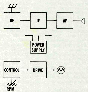
Figure 1 Largest division of equipment for 1-2-3-4 Servicing is Into
sections, one for each type of signal or operation.
---------------
Kinds of Circuits
SIGNAL or PULSE
Input
Output
Feedback
Bypass
Filter
Decoupling
Tuned (LC)
Time Constant (RC)
DC
Supply
Regulated source
Unreg source
Plate, Screen
Collector, Emitter
Drain, Source
Vcc
Bias
Grid
Base
Gate
Control
AGC
ACC
PLL
Keying
Speed Drive
Etc.
-----------------
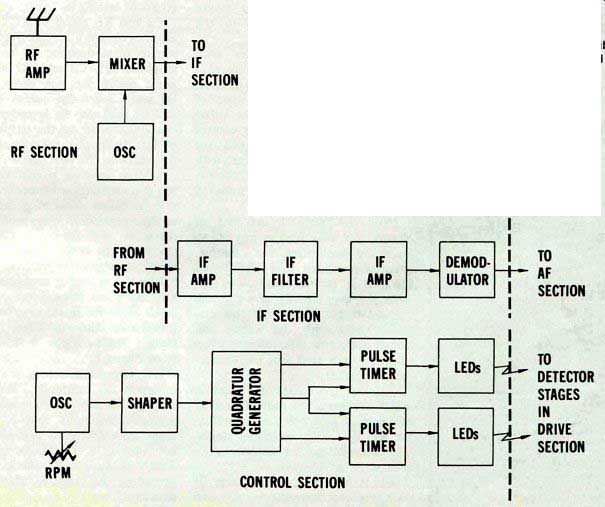
Figure 2 Stages are subdivisions of sections, for troubleshooting purposes,
and each one processes the signal or voltage in some way.
An oscillator stage, with a pot to manipulate frequency, supplies signal to a shaper stage. A quadrature signal generator stage produces pulse signals 90° out of phase but with frequency still controlled by the RPM oscillator. A pair of time stages, driven by the quadrature signals, delivers pulses by varying duty cycle (pulse duration compared to off time). These pulses are coupled by light-emitting diodes (LEDs) to detector stages in the section that follows.
Note that the signal originating in the oscillator has changed only in waveshape from the time it was generated until it becomes something entirely different at the LED stages. The signal no longer takes the form of electronic pulses.
Instead, the LED stages alter its entire character. It has become a modulated light signal. You are now dealing with optoelectronics.
LED stages are the final stages in this control section.
In comprehending the operation of this system, you can consider this section more easily stage by stage than by trying to absorb it all at once. The same is true when you set about troubleshooting a defect somewhere in the system.
CIRCUITS form stages
Sections and their interconnections illustrate the relationships of various functions in a piece of electronic gear. Then, inside each section, a breakdown into stages shows what's being done to the signal(s) inside the section.
Next, to understand how each stage works, you subdivide again into CIRCUITS. In general, there are two categories. One type of circuit handles signals; the other type works on dc supply or control voltages. Often, as you will see when you become familiar with 1-2-3-4 Servicing, control circuits can be considered as a form of signal circuit.
Note in Table 1 the list of circuits you may find in any stage.
Some are duplicative. For example, a coupling circuit may also be an input or an output circuit.
As you may already have guessed, COMPONENTS make up the circuits, along with the wiring and circuit foils and interconnect plugs and terminals that join the components together.
Consider the stages in Figure 3, which are from the radio of earlier examples. These are the demodulator and first audio amplifier stages.
The demodulator or detector doubles as an AGC stage.
T1 is an IF transformer. It comprises a tuned circuit and output circuit for the IF stage preceding. It is also a coupling circuit. It forms an input circuit for the demodulator stage centering around Dl. Diode D1 is the active component around which this final stage of the IF section is built.
C1-R5-C6 make up an AGC filtering network and are an output circuit for the demodulator diode, and coincidentally a control-voltage input circuit for whatever stages are AGC-controlled. You could also consider C1-R5-C6 a time-constant or RC circuit; charge-discharge times are chosen to anticipate AGC action yet smooth out any RF signals that survive the demodulator. They can also be considered a filter circuit.
Thus you see that what you label a circuit depends on what it's doing, and often on how you choose to look at it during a particular time. And the way you see each circuit usually determines how you go about testing it.
C2 and R1, along with C3, make up the coupling circuit for audio signals from detector D1 to audio amplifier Q1. C3 and R2 are the input circuit for this audio stage.
R4 and C5 are the output circuit, and C5 may also be considered the coupling circuit on the output side of Q1. It couples the signal from this stage .to the next one.
Seldom seen on partial schematics is power-supply capacitor C4. It may be called decoupling capacitor or filter capacitor. Along with series resistors, C4 forms a filtering circuit in the power supply, which decouples signals to or from stages fed by the dc line it connects to. It also filters out power-supply ripple.
All these are signal circuits. They transfer or otherwise affect signals.
Only a feedback circuit is missing from Figure 3.
DC circuits differ in that they maintain dc continuity. The path through R5 and any components or wiring connections that follow, it make up a dc circuit that could be considered a feedback circuit.
That's because AGC affects stages preceding the stage in which it is developed.
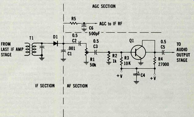
Figure 3---Circuits are, for 1-2-3-4 Servicing, the parts and wiring that
surround the main component of a stage. Old practice of calling stages "circuits" has
been abandoned for this technique.
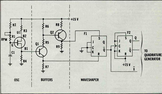
Figure 4---Circuits in some stages of an industrial control system. Where
ICs are involved, whole stage may be inside one IC, and all circuits
may be merely the wiring connecting IC into section.
Other dc paths are usually supply circuits for the active component the stage centers around. Q1 is an example. R2 and R3 make up a do divider that supplies bias voltage to the base of Q1. R5 is the only dc-conducting component in the supply circuit for the Q1 collector.
However, don't forget the wiring, the foil-to-component connections, and any intercabling and chassis plugs along the way from power supply to the stage in question.
The emitter supply circuit for Q1 appears on a schematic as a direct connection to ground. In reality, the path may be through a foil connection, a socket terminal and its foil connection, a length of printed or regular wiring, maybe even passing through a chassis or module plug before actual connection to chassis ground is completed.
You must be aware of, and on the alert for, these not-so-obvious circuit paths when you troubleshoot.
They are often where a defect hides.
Circuits in industrial equipment differ little. You must see them either as signal circuits, as control circuits (which may act like signal circuits), or dc circuits. Figure 4 shows an example, drawn from inside the sections and stages you have already seen. In the block diagram of Figure 2C, buffer stages were incorporated as part of the oscillator stage. They are shown separately in Figure 4.
Unijunction transistor U1 and its circuits form a relaxation oscillator stage. C1 is the discharge capacitor from gate to ground; it and R1-R2 form an RC circuit, making an input circuit for U1. R1 and R2 also form a bias circuit, a do circuit that supplies bias to the base of the unijunction transistor. R3 is the supply circuit that carries dc to base 2 of the UJT, and R4 completes the do path for base 1.
Also, R4 as a load resistor becomes the output circuit of U1.
Input circuit for Q1 consists of a connection from base 1 of U1 and input load R4. Resistor R4 also makes up the bias circuit for the base of Q1. You can't find much better examples than these of how one component or circuit can perform duplicative services. You name each circuit according to the stage and what purpose within that stage you're concerned with at the moment.
The base, emitter, and collector circuits of Q2 carry much the same components as Q1, and they perform similar services in the stage.
Two flip-flops are the only components in the waveshaper stage.
Their wiring appears to be the only circuitry. But in a sense, R9 and R7 are part of the input circuits of F1, to the set and reset terminals.
Both flip-flops are J-K types. But F1 is wired up to function as a simple R-S flip-flop, and F2 is wired as a divide-by-two counter.
Their outputs, in various phase relationships, drive the quadrature generator stage that follows.
One other fact you discover when you begin chasing a defect in the waveshaper stage: Both flip-flops are inside a single integrated circuit. You can actually troubleshoot them only by checking do supply, input signals, and output signals and even then only signals that are brought to IC pinpoints. Rather simplifies servicing, doesn't it?
-----------------------
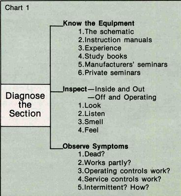
Chart 1
Diagnose the Section
Know the Equipment
1. The schematic
2. Instruction manuals
3. Experience
4. Study books
5. Manufacturers' seminars
6. Private seminars
Inspect-Inside and Out-Off and Operatin
1. Look
2. Listen
3. Smell
4. Feel
Observe Symptoms
1. Dead?
2. Works partly?
3. Operating controls work?
4. Service controls work?
5. Intermittent? How?
------------------------
Four servicing steps
Organizing a large complicated electronic control system in the manner just described forms the bias of 1-2-3-4 Servicing. Now you need only become familiar with the numbered steps, and you are in position to apply 1-2-3-4 Servicing to any factory electronic system.
STEP 1--DIAGNOSE the Malfunctioning SECTION
Often you can do this by analyzing symptoms.
You may have to put some test equipment to work. In larger systems, built-in monitoring devices or test jacks make diagnosis easier.
Your goal is to move as quickly as possible to the section that really has malfunctioned. You thus eliminate time wasted in sections that would work okay if the bad one were operative.
Devise tests that inform you quickly whether a particular section is working or not. The time to do this is when the equipment is functioning normally, especially when it first goes on-line. You can often learn much from the team that installs a complex piece of electronic gear. Notes that record a few key measurements or waveforms during normal operation can be worth their weight in gold when the system breaks down.
Even without such advance planning, however, you can make some wise assessments by studying the schematic and the manufacturer's instruction manual. Most important, however, at this step in troubleshooting, is the act of mentally dividing the system into manageable sections.
Chart 1 lists methods by which you diagnose a malfunctioning section, even in very complex equipment.
STEP 2--LOCATE the Faulty STAGE
Even here, you can still make some quick and accurate decisions if you are familiar with equipment operation and will observe symptoms carefully. Chart 2 offers suggestions.
Generally, however, troubleshooting know-how enters here. Injection troubleshooting is the same for analog (linear) or digital circuitry.
Of course you need a generator that supplies the needed signal. Adjustable pulse generators make excellent injection sources. If you buy one, choose the kind that lets you adjust pulse duration and duty cycle over a wide range.
Signal tracing generally proves more popular than injection. An oscilloscope can track down just about any signal function (or malfunction). If you're not comfortable with a high-quality, dual-trace, triggered oscilloscope, take steps to get that way. No other instrument will be of more value to you in locating a faulty stage in a complex control system.
In certain transistor stages, voltage tests are some help. But as a rule, you should deal with signals, either analog or digital, when tracking down a faulty stage.
Do locate the faulty stage. Do not hunt haphazardly for a defective component. There are too many stages in most equipment for you to guess your way to a defect in any reasonable time. Go into the job logically, and you'll have the system back on-line as quickly as anyone could.
----------------------
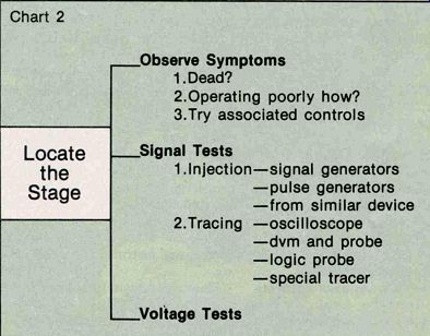
Chart 2
Locate the Stage
Observe Symptoms
1. Dead?
2.Operating poorly how?
3.Try associated controls
Signal Tests
1. Injection-signal generators
-pulse generators
-from similar device
2. Tracing-oscilloscope
-dvm and probe
-logic probe
-special tracer
Voltage Tests
-------------
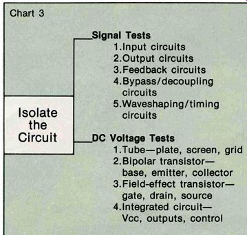
Chart 3
Isolate the Circuit
Signal Tests
1.Input circuits
2.Output circuits
3.Feedback circuits
4. Bypass/decoupling circuits
5.Waveshaping/timing circuits
DC Voltage Tests
1.Tube-plate, screen, grid
2.Bipolar transistor base, emitter, collector
3.Field-effect transistor gate, drain, source
4.Integrated circuit Vcc, outputs, control
------------
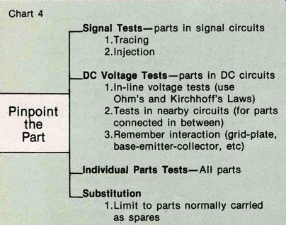
Chart 4
Pinpoint the Part
Signal Tests-parts in signal circuits
1.Tracing
2.Injection
_DC Voltage Tests-parts in DC circuits.
Lin-line voltage tests (use Ohm's and Kirchhoff's Laws)
2.Tests in nearby circuits (for parts connected in between)
3.Remember interaction (grid-plate, base=emitter-collector, etc)
.Individual Parts Tests-All parts
_Substitution
1.Limit to parts normally carried as spares
------------
STEP 3--ISOLATE the Defective CIRCUIT
When you have the one troubled stage located, you almost have the breakdown cured. Often, the stage may be on a module card that you can replace. Then hunt the defective circuit and part at your leisure.
Unfortunately, small factories seldom stock spare boards for their control systems. You're faced with chasing the trouble all the way to the specific part that caused the stoppage. So, you isolate the defective circuit. That way, you don't have to make tests in a lot of unnecessary circuitry.
Chart 3 lists the ways you might go about it most expeditiously.
These techniques apply to tubes, to transistors of various types, and to integrated circuits.
In coupling circuits, you obviously test for signals. In supply circuits, it's dc faults you're looking for.
Probably the most difficult to test are feedback circuits. Yet, there's a simple technique. Take one end loose. Make sure signal drives the network, either from the stage that furnishes the feedback or from a generator. Then see if the signal appears at the other end. Also verify that the feedback network properly affects the signal.
Decoupling and bypass circuits are often overlooked. They're easy to test. You have two methods.
One, connect an oscilloscope across the bypass capacitor; there should be little or no signal across it. Two, bridge a good capacitor across the suspected one and see if that cures the malady.
STEP 4--PINPOINT the Bad Part
As often as not, the quickest way is by substituting a new part. Any well-equipped factory maintenance department stocks spare parts for its systems. Without parts, expect delays when breakdowns do occur.
However, larger and more expensive components compel you to make sure. Chart 4 offers suggestions for pinpointing which part has become defective.
You can test some parts with signal tests, like a capacitor you suspect of being open. Or with dc tests, as perhaps a capacitor or transistor you suspect of leakage.
Instruments that test specific parts can be handy, but the maintenance technician with ingenuity doesn't need every instrument in the catalog.
However, certain instruments save a lot of time. Transistor testers, capacitor checkers, and the like are worth their cost only if the save time and speed repairs. Too, you can do some preventive trouble shooting with a leakage checker, if there are periods when the system is shut down long enough for maintenance tests.
Every time a new system is installed in your plant, figure out what new instruments are needed to test it and its parts. You could be severely handicapped if you have to "make do" when testing parts that fail regularly or even occasionally.
Pulling it all together
By now you probably see how basic and fundamental 1-2-3-4 Servicing is. If you're a top-notch technician who uses this kind of good-sense automatically, bravo! This serves as a review, and corroborates that you're on the right track.
If you're just entering the field of industrial maintenance, however, you'll find 1-2-3-4 Servicing about the most helpful tool that could be put into your hand.
As we said at the beginning, 1-2-3-4 Servicing does not constitute a panacea. It performs no miracles. Only you can turn yourself into a grade-A maintenance technician. You do that by observing these pointers: Learn intimately the systems you must maintain. Attend manufacturer seminars if they're available.
Insist that the manufacturer supply manuals you can study. Read books that describe your company's control systems, and the processes being controlled.
Keep yourself up-to-date technologically. You can't survive among factory electronics without a deep practical knowledge of solid-state, of digital electronics, and of LSI techniques.
.Know how to use modern instruments, in particular the triggered oscilloscope, adjustable pulse generators, logic probes, and the newer, even more sophisticated timesavers for control-systems testing.
Find and adopt a logical troubleshooting method-if not 1-2-3-4 Servicing, then another. You cannot keep your factory running smoothly if you use haphazard troubleshooting.
Also see: Testing solid-state devices in factory gear