By Wayne Lemons
When taking care of industrial electronic equipment, the name of the tune is "Get the unit back on-line-fast!" Successful maintenance technicians develop as many shortcuts as possible. Sometimes you remember which part most frequently causes a particular symptom; or the manufacturer's manual may have suggestions. Other times, you exchange a spare subassembly for the defective one. But, if the symptoms are unfamiliar, or there is no spare, you're on your own.
Pretty soon (you hope) you have isolated the trouble to one specific area in the complex system. All that remains is a circuit-ful of parts to be tested, to identify the culprit as quickly as possible.
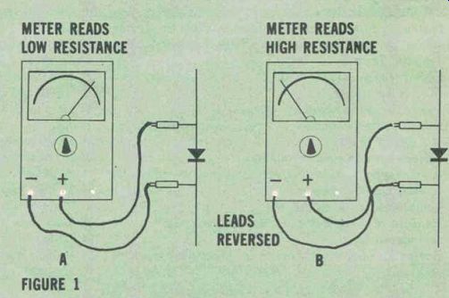
Figure 1 "Diode action" means an ohmmeter shows low forward
resistance and high reverse or backward resistance.
Many parts in today's factory controls are solid-state. And even long-experienced technicians occasionally butt up against a time problem when testing solid-state devices. Here are some reminders (nuts-and-bolts ways of testing) in-circuit whenever possible, and with simple equipment. They should help.
Diodes
The most common solid-state component of all is the silicon diode. This simple device forms a one-way street for current, allowing it to flow in one direction but not the other. Diodes appear as rectifiers, as guides for direct current or voltage, as pulse rectifiers and clippers, for bias compensation, as circuit protectors, for blocking reverse current, to suppress arcs and inductive kicks, and in other uses.
With a diode out of the circuit, you can easily check it with a regular ohmmeter, in the manner of Figure 1. This test should exhibit diode action, that is, low resistance (20 ohm or so) in one direction and high resistance (more than 1M ohm ) in the opposite.
Exact resistances depend on the type of meter and ohmmeter range used to take the measurement. For example, a diode that reads about 20 ohm on the Rx1 scale may indicate 100-o or more on Rx10, and as much as 1000 ohm on Rx100. Any diode with a. forward reading more than 50-o on Rx1 is probably made of silicon rather than germanium.
An ohmmeter cannot reveal that a diode's junction may break down under operating voltage. Nor can it distinguish a regular diode from a fast-recovery type, or a Zener. Still, within limits, ohmmeter checking is valid, quick and extremely convenient.
In-circuit diode tests
Testing diodes in-circuit, even with an ohmmeter, has two advantages over out-of-circuit tests.
First, you know (unless someone earlier made an incorrect replacement) that the diode is the right one, and second, that it is connected in the right direction. In other words, you don't have to worry that the diode is, for example, a Zener when it should be a regular diode, or a slow-recovery type when it should be fast.
Diodes, especially silicon diodes in rectifier or other high-current use, normally go bad in one of just two ways. They short, about 85% of the time, or open the other 15%. This makes in-circuit checks with an ohmmeter valid just about always.
First you connect the ohmmeter leads across the diode. A low reading one way and a high reading the other (diode action) tells you the diode is okay. You can move on to the next part. Of course the higher reading may not be over a megohm.
There may be shunt resistances in the circuit. You need to be sure only that there is a difference between the readings.
If, on the other hand, the diode measures less than 5-ohm or so, in either direction, it is suspect immediately. The reason? Only a shorted diode, or one with a really low resistance shunt, measures less than 10 to 15 ohm on a regular ohmmeter.
Moreover, there are not many circuits in which shunt resistance across a diode is less than 20-ohm. In Figure 2, for example, a diode is used to damp out inductive kick from the relay. The coil measures several hundred ohm dc. So you still find diode action across the diode.
If the coil is 500o, the ohmmeter reads 500 n in one direction and only the forward resistance of the diode, perhaps about 20 ohm or so, when the leads are reversed. That 25-to-1 ratio certainly indicates normal diode action.
Misleading in-circuit readings
An open diode in either a full-wave or bridge rectifier stage may not be missed. This is because another diode is always in parallel with any open diode, through the secondary winding. If transformer winding resistance is low, the slight discrepancy in measured forward resistance might not be considered significant.
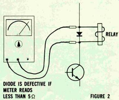
Figure 2---A diode can be judged even both ways means it's shorted when
shunted by a coil. Less than 5-ohm.
For this reason, if two bridge rectifier diodes exhibit a few ohms difference in forward reading, it is a good idea to check further.
Disconnect one lead of one diode and test across both diodes again.
An open diode like this often has little effect on the dc output of a full-wave rectifier circuit. In fact, the equipment being supplied power may seem to work normally.
Other times it works marginally, making you sense vaguely that something is not up to par, but leaves you not quite sure what it is.
The open diode may change the operation to half-wave, thus cutting ripple frequency in half. But when filtering is ample, this too may go unnoticed. In bridge or full-wave circuits used for other than power supply, an open diode usually brings immediate circuit malfunction.
Leakage
It is rare for leakage in high current diodes to cause trouble.
When leakage does occur, heat inside the diode generally causes it to short or open almost immediately. In low-current and pulse circuits, however, leakage may cause either steady or intermittent troubles. Dependable in-circuit testing for leakage is not possible when there is an inductive, resistive, or forward-conducting solid-state path in parallel with the diode.
Even with the diode out of the circuit, leakage may fail to show up during an ohmmeter test. Sometimes, leakage is avalanche-type, occurring only at some definite reverse voltage and leaving reverse current perfectly normal below this voltage level. Even high-current diodes occasionally show good diode action, yet break down under load.
Measurements for this kind of leakage are best done as described later.
Zener diodes
A Zener or avalanche diode exhibits diode action with an ohmmeter, the same as other diodes. At a certain critical voltage, however, a Zener diode suddenly draws heavy reverse current. , Because of this phenomenon, Zeners make good voltage regulators. They can also set a reference voltage for more complex solid-state regulators.
Regular ohmmeter testing proves whether a Zener diode is open or shorted. But an ohmmeter cannot determine at what voltage the Zener avalanches.
Nor, in many cases, will the ohmmeter show if the Zener is leaky-and leaky Zeners are fairly common.
A defective 24V Zener may reduce voltage across itself to 15V or 8V, or whatever. To test this, turn on the equipment (if you can) and see whether or not the rated voltage develops across the Zener (Figure 3). If the voltage measures low, there are four possibilities: the Zener is defective; the load following the Zener is excessive; the voltage feeding the Zener is low; or the series limiting resistor preceding the Zener has changed' to a. high.
value. Unless a slightly higher-than normal output voltage might damage some part of the circuit (and usually it won't) the best quick test for a defective Zener is to disconnect one end and check the output voltage. If voltage rises where the Zener was connected, the supply voltage and limiting resistor are okay, and the load is not excessive.
One visible sign of a leaky Zener is a burned or discolored limiting resistor. If the resistor is wirewound rather than carbon, it may become warm enough to discolor the board around it. Sometimes the Zener will itself overheat enough to discolor the board.
Another way to check a Zener in-circuit is diagrammed in Figure 4. You remove the load from the Zener and check to see if the voltage across it stays normal.
However, this test can be misleading if the limiting resistor happens to have changed to a high value, or if regulation of the supply voltage is poor.
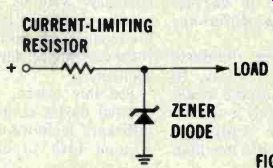
Figure 3 A discolored current-limiting resistor, or one that has changed
value, may call attention to a defective Zener.
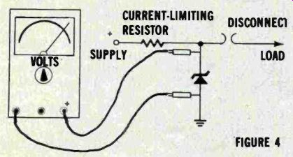
Figure 4 Disconnecting the load will help you decide if a Zener diode
is leaky.
But first make sure the supply voltage and the current-limiting resistor are okay.
Replacing diodes
The factory-recommended diode replacement is almost always best.
You can expect that it exhibits the correct electrical specifications and that it fits in the niche provided.
But there are times when a replacement may not be available immediately, or when modifications need to be made. The following important parameters need to be considered whenever you choose a replacement diode: Peak reverse voltage (PRV). This refers to how much reverse voltage a diode can withstand without breaking down or zenering. For safety, the PRV rating should be about double the peak voltage expected. The extra margin minimizes breakdowns due to voltage transients and surges. Figure 5 charts the amount of PRV you should allow for in different kinds of rectifier circuits.
Forward average current (I_0). Even small silicon diodes may have an I_0 rating of I_A or more. Large silicon diodes with heat sinks may be able to carry 200A or more.
Repetitive peak forward current (IFRM)
This parameter is important for diodes that are followed by capacitor-input filter circuits. The diodes supply current for considerably less than a half-cycle, restoring the charge in the filter capacitor only on peaks. This may mean that the forward current during each peak may be several times as high as the average current required. As a rule of thumb, most silicon diodes can safely handle these peaks if the IFRM is five to ten times the Io.
Intermittent surge current a diode can withstand also becomes important. The ISURGE or IFSM specifies the amount of current a diode can safely handle for a short period of time-usually one cycle at 60Hz or about 17ms. This rating is especially important when a power supply is first turned on. The input capacitors appear for an instant as a short circuit, and require a heavy surge of current from the rectifier diode.
If you can't find the specification as to surge current for a particular diode, as a general rule figure that a silicon .diode can withstand surge current 15 or 20 times the average forward current rating. A few may withstand 50 or more times the I_0 rating.
Fast-recovery diodes
For circuits in which a diode must react or switch at a rate higher than a few hundred hertz, a regular silicon rectifier diode cannot turn off quickly enough to stop current flow between cycles.
In low-power, higher-frequency circuits, a slow diode replacing a fast one may result in a circuit malfunction. (An IN914 is a popular fast diode for low-power circuits). In higher-power circuits, such as one in which pulses are rectified to supply dc power, a slow diode not only causes circuit malfunction but overheats quickly due to heavy reverse current. It can also damage other parts before burning itself out, especially if adequate circuit protection is not provided.
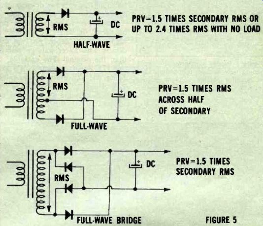
Figure 5 Approximate PRV expected across diodes in sine-wave rectifier
circuits. For example, if rms measured across secondary of transformer
C is 50V, PRV across any diode is about 75V. Replacement diode should
be rated for at least
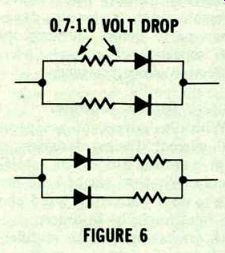
Figure 6 Diodes may be connected in parallel successfully only if resistors
are placed in series. Select resistor value so that each resistor drops
approximately 0.7 to 1V.
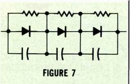
Figure 7 Diodes connected in series should have resistor-capacitor shunts
to equalize reverse voltages across them and to suppress cutoff transients.
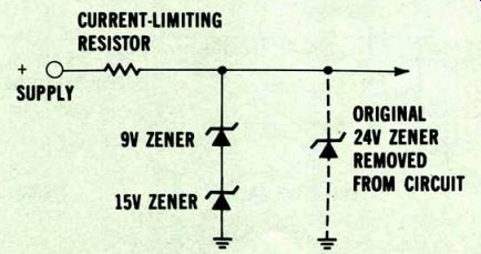
Figure 8 --Two (or more) Zener diodes may be connected in series to replace
a single higher-voltage Zener. Zeners should not be paralleled.
Diodes together
With the advent of inexpensive high-current diodes, designers seldom parallel diodes in rectifier circuits. Yet, you might have occasion to do it yourself. A word about the rules might be in order.
If, for example, a 2A rectifier is needed and only 1A diodes are available, they may be connected in parallel. But because of normal differences in the diodes, even of the same type, one may conduct considerably more current than the other. Early failure of one could occur. To prevent this, you should connect equalizing resistors in series with each diode, as Figure 6 shows. The resistors should be selected to drop about 0.7 to 1V in normal operation. Be sure they have ample wattage ratings.
It is rather common practice to connect solid-state diodes in series to attain higher PRV ratings.
However, equalizing resistors and capacitors are recommended, and Figure 7 illustrates how to connect them. The resistors divide the voltage more equally across the diodes when they are reversed biased. The capacitors protect any diode that cuts off slightly before a neighbor does.
Resistor values should be roughly 40 times the PRV ratings of the diodes. For example, if a diode is rated at 600 PRV the resistor across it should be about 240,000 (400 x 600). Equalizing capacitors in 60Hz circuits should be about 0.01pF. Use disc ceramic types, with a voltage rating approximately twice the expected PRV. Zener diodes may be connected in series to obtain a higher regulated voltage (Figure 8). Generally no equalizing resistors or capacitors are needed.
When two or more Zeners are connected in series to replace a higher voltage Zener, you can use devices with lower wattage ratings than the original. For example, if two 12V Zeners replace a 24V 1W Zener, the 12V units may be rated %W. However if a 15V and a 9V are used, only the 9V unit may be rated 1/2W. The 15V unit should be rated at 1W since it will need to dissipate more than half the power consumed in the circuit.
Testing Replacement Diodes
If you have any doubt about a replacement diode, check it before installation. Checking parts you have already replaced can confirm your testing procedures and perhaps relieve your mind that the repair is complete. Moreover, someone may have inadvertently mixed regular diodes and Zener diodes.
Unless type markings are legible on the diode, only testing can distinguish which is which.
Both regular and Zener diodes can, of course, be tested with commercial testers. But for the times when a tester isn't available, the method described here works.
You need only an unsophisticated variable source (it doesn't even have to be regulated), a limiting resistor, and a voltmeter. The limiting resistor is not critical; generally, a 1000-ohm 1W type is suitable for most testing.
Set the supply to zero or low voltage. Connect the circuit as drawn in Figure 9A. Gradually turn up the voltage while watching the meter. When the diode zeners, the voltmeter reading stops rising. Increase the power supply voltage only enough further to make sure the voltage rise has actually ended.
You don't want to exceed the wattage rating of the diode.
For a bit of sophistication in this test, add a milliammeter in series with the resistor. The milliammeter will suddenly start indicating current when the diode zeners. Adjust the power supply for a reading of 10mA for small Zener diodes, or up to 100mA for a high-power Zener.
The voltage you measure across the Zener diode with this much current flow is the actual avalanche point of the Zener. This should be very close to its voltage rating.
If your do power supply can furnish high enough voltage, the circuit of Figure 9A can also be used to find the PRV rating of a regular diode. If, for example, a regular diode zeners at 100V, then it should not be used in a circuit where PRV exceeds 50V. For PRV checks, the series limiting resistor should be raised to 10k-o 1W, to prevent excessive reverse current through the diode if the test voltage is advanced too far. Or, monitor the milliammeter and keep reverse current no more than about 10 mA. A fixed dc supply can also be used for testing Zener diodes as long as its output voltage exceeds the value needed. Figure 9B shows the hookup. The limiting resistor value, as a rule of thumb for almost any diode, can be about 100 St for each volt of drop expected across it.
For example, if you want to check a 24V Zener with a 50V supply, the resistor value should be in the neighborhood of 2600 it (50 24 = 26 x 100 = 2600). A 2700 ohm resistor would do because the value is not critical. You may also want to connect a milliameter in series to monitor test current.
Checking transient-protection diodes
Failure of a transient or surge protection device may not be immediately apparent. In fact, one may be defective for quite some time before you realize it. One clue is more than a usual amount of failures in other diodes, transistors or ICs.
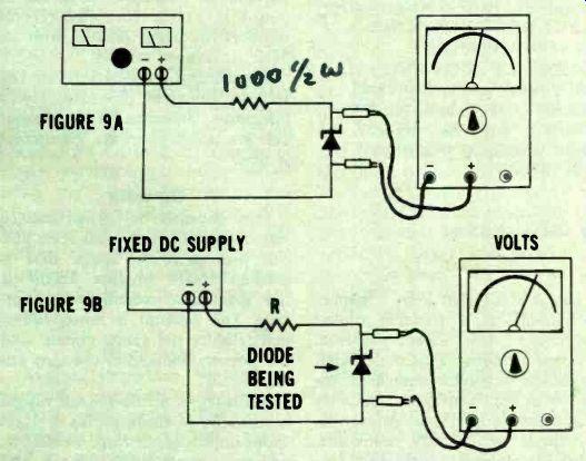
Figure 9---Whether variable or fixed, dc supply can be used to test
Zener diodes.
Output voltage must exceed rating of any Zener to be tested. Can test 'PRV of regular diodes, too.
Figure 10---Some devices for reducing transient voltage spikes coming from the power line. If these devices open, you may not see Immediate changes in circuit operation. But failure rate of other components may increase.
There are at least two types of transient protection for power lines.
The most common is simply a capacitor. The capacitor shows high reactance to the power-line frequency but fairly low reactance to sharp transient-voltage spikes. This causes the spikes to be absorbed or, more correctly, to be integrated to low levels.
A solid-state device for suppressing voltage spikes compares essentially to two Zener diodes in series (Figure 10). When a voltage spike exceeds the set level, one of the Zeners fires-which one depending on polarity. Its mate, which is forward-biased for that polarity, conducts normally. The spike is therefore clipped at this level and prevented from reaching the remainder of the circuit.
These devices obviously cannot be checked with an ohmmeter. If enough power-supply voltage is available, you can check them by wiring up either circuit of Figure 9, right in the equipment. Use a limiting resistor that reduces current in the Zener to no more than 10 mA or so. Reverse the hookup and test the Zener combination for suppression of both positive and negative spikes. Some leeway is permissible between the actual avalanche voltages in the two directions.
Next time, quick testing for many other solid-state devices in factory gear such as SCRs, Triacs and Diacs will be discussed.
Also see: ALU the microprocessor calculator