This is Sam's last Technical Notebook because he is not writing articles at present. Sam regrets that his time did not permit him to answer all of the letters. However, he read (and appreciated) them and thanks you for your interest.
By J.A. "Sam" Wilson, CET
Contest winner
Several months ago, I offered a copy of my industrial electronics book as a prize to the first reader who submitted a practical counting circuit that skipped number six each time it counted from zero to nine and repeated.
Many schematics and suggestions were sent in. Several readers mailed materials taken from books or magazines. These could not be printed without permission from the author or publications, but they were interesting.
A surprising number of circuits skipped both six and seven. How ever, the object was to include all numbers from zero through nine except for number six.
Several readers invented complicated stories about how to use such a counter, but no one suggested a practical application.
A few sophisticated circuits used a read-only memory (ROM) or read-write memory IC, but the winning entry arrived earlier.
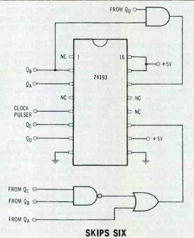
The winning schematic was sent by John Jones of Albany, GA, and his circuit is shown in Figure 1.
Imaginary number
High school algebra books refer to √-1 an "imaginary number." According to the usual explanation, there is no number that can be multiplied by itself to give-1 as a product. Then a chapter full of problems is given.
The term "imaginary" is an inappropriate descriptive word for the square root of minus one. It seems to imply that the term is worthless for practical uses and can be discarded or ignored. That is not true.
It is very valuable in the study and mathematics of ac networks, where the term is called the j operator.
An operator is a mathematical symbol that describes the procedure to be followed. For example, the math problem 4+6 uses the opera tor +. Other popular operators are -, x and =.
Incidentally, an operational amplifier (op-amp) first was designed to perform addition, subtraction, multiplication and division as well as other basic math operations, and it was used extensively in analog computers. Op-amps became even more versatile and valuable when packaged in integrated-circuit form.
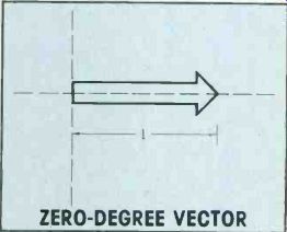
Refer to the vector in Figure 2.
Its value is +1 and it lies in the zero-degree or standard position.
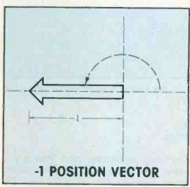
In Figure 3, the vector has been rotated 180°. Its value now is equal to -1. Of course, purists will argue that the value of this vector never can equal -1, because it's impossible to have a negative length.
However, the point of the vector is at -1, so it can be said to be in the -1 position.
To rotate the vector from its Figure 2 position to the position in Figure 3, the vector is multiplied by -1.

Figure 1 John Jones sent in this winning design for a zero-through-nine
counter that skips six. QA, QB, QC and QD of the 74193 IC are outputs
to a 7-segment decoder that drives an LED display.
Therefore, if multiplication by -1 rotates a vector 180°, by what must it be multiplied to rotate the vector only 90°? Answer: multiplication by √-1 rotates it 90°. This must be correct, for when it is multiplied again by it moves to the -1 position.
√-1 x √-1=-1
In this case, the operator j commands you to rotate the designated vector by 90°.
Relating operator j to electricity
Ac current in a purely inductive circuit lags behind the voltage by 90°. It would be proper to say the current vector is operated on by a j.
Ac current in a purely capacitive circuit leads the voltage by 90°. If j rotates a vector 90° for a lag, then -j should operate on it for a 90° lead.
The expression R+jXL means that XL is at an angle of 90° relative to R. A +j causes a counter clockwise rotation. So the expression R-jXC indicates that XC is clockwise by 90° from R.
To summarize, j simply is an operator that rotates a vector away from the standard position. A +j rotates it 90° counterclockwise, while a -j rotates it 90° clockwise.
The term vector indicates a magnitude and a direction. In electrical circuits, the arrows of vectors represent magnitude and phase differences. Therefore, they properly should be called phasors rather than vectors.
Repetition makes it true Lewis Carroll said in The Hunting of the Snark, "What I tell you three times is true." Repetition does enhance credibility.
I have heard the following story more than three times. Therefore, it must be true. There was an intense but friendly rivalry between engineers of Swiss and American watch factories. Finally, the Swiss engineers made a spring so delicate that observation of it required a microscope. They sent it to the American engineers with the challenge, "Match this." Before the Americans sent the spring back, they drilled a tiny hole in the end of it.
The story took on special significance for me last spring when one of my brighter students placed a circuit board on my desk. It was a breadboarded digital counter that first counted all odd numbers between zero and 20, then the even numbers were counted, and finally it counted zero to 20 by ones.
"Match this," he said in an arrogant manner. I drilled a hole in the counter.
Last charge for the wire capacitor Letters came in for several months following previous descriptions of the marvelous infinite capacitance made from a short length of solid wire.
A few readers suggested that the wire really was made up of an in finite number of capacitors in series, thus making the final value equal to zero. Others said the circuit equivalent is an infinite capacitance paralleled by a zero resistance leakage path, as shown in Figure 4. However, no one has argued successfully against the wire capacitor having a very thin air space for a dielectric.
Two correct answers Richard Colby of Honolulu, HI, doubts the completeness of my answer to a question from Allen Daubendiek (Beatrice, NE) about a question in one of my CET Practice Tests. The schematic and original question are printed in Figure 5.
The corrected answer given on page 42 of the September 1978 issue of Electronic Servicing was number four. Colby replied that although answer four is correct, answer three is also equally correct.
In fact, answer four precedes answer three in the circuit analysis.
Good tests should not have two correct answers to any question. So, Colby wondered if the jumper could be moved to other points that would make answer two the correct condition.

Figure 2 The value of this vector is +1. It lies in the standard or
zero-degree position.

Figure 3 Rotation of the vector by 180 deg brings it to the -1 position.

Figure 4 (A) This is the original drawing of the wire capacitance. (B)
Some readers believe the wire has infinite capacitance but is paralleled
by zero resistance.
Quoting from his letter: "If the short is changed to the Q1 collector and the Q2 emitter, the situation is similar to Q1 saturation. The emitter is made more positive by voltage from R3. This is lower forward bias for Q2, so its reduced conduction increases the collector voltage. This increases the forward bias at the Q3 base and causes heavy current to flow through Q3." The corrector is corrected--One of the difficulties faced by those who make up tests is that a lack of vigilance and crosschecking can allow several answers to be correct rather than just one. It is interesting to note that Colby also fell into the same trap he tried to correct.
His suggestion of moving the jumper does make answer two correct. Unfortunately, it also makes answer four correct. (Answer four stated: Transistor Q1 would be cut off.) Perhaps one could argue that the new short does not affect the R1/R2 base voltage divider, so it could not have decreased the base voltage. That's true. (In fact, the reversed bias increases the base-to-ground voltage.) However, the emitter voltage rises above the base voltage because of voltage from R3 (usually a low-value resistor). Re member, the emitters of Q1 and Q2 are connected together; therefore, Q1 is biased to cut off, and answer four is correct.
Because the Q1 and Q2 emitters are connected together, the new jumper position gives the same symptoms and voltage readings as a collector-to-emitter short in Q1.
Check for such a short immediately after a voltage reading shows the transistor bias is reversed but collector-emitter current is flowing.

Figure 5 Question: In this circuit, which of the following will occur
when the base of Q1 is shorted to the emitter of Q2?
(1) Transistor Q2 will be destroyed.
(2) Heavy collector current will flow in Q3.
(3) The Q2 collector will become less positive.
(4) Transistor Q1 will be cut off.
In the practice test, the correct answer is listed as number two. That is not true. Instead, both answer three and answer four are correct. Reader Colby suggested the jumper should be connected between Q1 collector and Q2 emitter, which would make answer two correct. Is anything wrong with such reasoning?
Also see:
Sam Wilson's Technical Notebook (Aug. 1979)