DYNAMIC SPEAKERS
Put these old-time speakers back in action.
One of the most important parts of any radio is the loudspeaker, and old-time radios had speakers which were quite different from the speakers of today. (Editor's Note: although a loudspeaker really consists of two main parts, the speaker driver and the speaker enclosure, when we talk about a loudspeaker we are usually referring just to the driver.) Modern speakers have just two connections, which go to the voice coil. The magnetic field that the voice coil is suspended in is created by a strong permanent magnet. But speakers of yesteryear didn't have permanent magnets-magnetic materials at that time hadn’t been developed to the high degree that they are today-so the magnetic field for the voice coil had to be created by an electro-magnet; a coil of wire with a strong direct current going through it. For that reason early speakers had four (sometimes five) connections. Two (or three) of these connections went to the field coil.
This article describes the old-type speakers and how to repair or replace them. To learn about field-coil loudspeakers, which is what radio had between the late Twenties and the early Forties, read on.
How to Do It
Since electro-dynamic speakers are no longer made there are two basic ways to get that old radio to play again.
1. Have the original speaker repaired, i.e., replace the cone or have a new field coil installed.
2. Replace the old speaker with a new modern permanent magnet type.
To enable you to make an intelligent choice, I will present a detailed account on how to replace the original speaker. Having the original rebuilt means sending it off to a mail order repair shop. But first, let's review the loudspeaker story, and refresh your memory on the different types of speakers usually found with antique radios.
Early Speakers
First of all, there are two basic types of speakers found in radios made between 1920 and 1950. The first radios only used headphones, sometimes called earphones. Headphones limited the number of persons that could listen to a radio at one time. They were reasonably sensitive, worked with crystal radio sets, or with 1-tube battery-operated radios. The basic design of an earphone consisted of two coils of fine wire, with laminated cores inside the coils, surrounded by a horse-shoe-shaped magnet.
Suspended a few thousandths of an inch above the coils was a very thin, soft iron diaphragm that vibrated in unison with the received audio frequencies. The diaphragm produced sound waves.
Quite soon, someone mounted the earphone on a horn and the sound was then loud enough for the whole family to enjoy. Soon manufacturers were making larger headphone units to be mounted on larger horns. Distortion was a problem with the limited power handing ability. The next step was to build a cone type speaker, and the center-pin driven reproducer. The above types all fall into the category of Magnetic Speakers. Meanwhile out in California, Magnavox began to build a horn-type dynamic loud speaker. This speaker produced more power and better tone. Since the battery sets of that time used a 6-volt storage battery for the tube filaments, the speaker field also operated on 6-volts. The biggest drawback to the dynamic horn speaker was its size.
The consumer was asking for radio that was self-contained with speaker and set all hidden inside a wooden cabinet. The dynamic cone speaker was introduced about the same time that AC operated radios became popular.
Dynamic Speakers
Dynamic Speakers had a paper cone with a voice coil cemented to its center. The voice coil was a cylinder of paper from 1 to 2-inches in diameter, depending on the power handling design of the speaker. One or more layers of insulated magnet wire was wound on the voice coil and ultimately connected through an impedance matching transformer to the audio output stage of the radio receiver.
Centered inside the voice coil was a soft iron pole piece which in turn was surrounded by a field coil wound with thousands of turns (except in car radio speakers) which when connected into the radio high-voltage circuit produced a magnetic force in the pole piece. This speaker was called an electro-dynamic speaker. The illustration shows this kind of speaker, plus a typical circuit diagram using an electromagnetic (EM) speaker. It took a lot of electrical power to magnetize the pole piece, so when more efficient permanent magnets were developed manufacturers began to make PM dynamic speakers.
The EM dynamic speakers used in auto radios, at this time, had only 4 or 6-ohms resistance, and it took 1 to 1.5 amperes to excite the field. If you remember the automobiles that had 6-volt ignition systems you will also remember that they were never too good in winter.
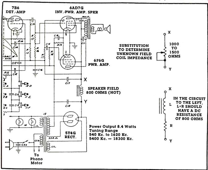
------- When you want to substitute a modern speaker for an old
one that had a speaker field coil, you need to replace the lost impedance
in the circuit. Unlike this schematic of a Zenith Model 75681/2 many
old-time schematics don't always include the value of the coil. Determine
this with the top circuit and replace it with the bottom one.
When the PM (permanent magnet) speaker was introduced, auto radio manufacturers were the first to use them. Later they were used in portables and house radios. Alnico V was the magnet used most successfully in speakers. Generally speaking, a larger magnet will permit the speaker to handle more power.
Thus a small 4-inch speaker may have a half-ounce magnet while a 15-inch speaker may have a 2-to 3-pound magnet. Replacing a PM speaker is no problem since replacements are readily available at all radio parts stores.
Replacing an EM or field coil speaker is a much bigger problem. To start with, the field coil had a certain amount of inductance and therefore it acted as a filter choke in the "B" power supply circuit. The resistance of the field coil was also the resistance that determined the "B" supply voltage supplied to the tubes in the radio. So when replacing an EM speaker with a PM we have a couple of important factors to consider. The first factor is physical size. Whenever possible, always use the largest PM speaker that will fit the allotted space. The larger speaker will reproduce bass notes more efficiently than a small speaker. If you use a smaller-than-original size speaker, you will have to make an adapter board with the proper size hole for your new speaker and make it large enough to cover the old hole. Without going into acoustic theory, I would advise you to never leave an opening around the speaker cone. To produce the same amplitude and frequency tone range as the radio did when new, you should try to return the set to its original baffle condition.
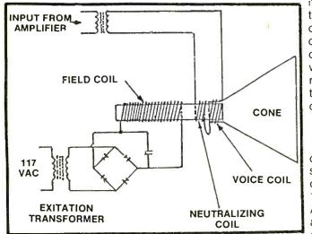
above: This schematic representation of a dynamic loudspeaker shows how
the parts relate to each other. The field coil energizes the core (now
permanent magnets are used) so that it is a steady field magnet. The fluctuating
magnetic field on the voice coil moves the cone over the core.
The Choke Coil
The second factor is to introduce some inductance into the power supply circuit in place of that lost by removing the speaker field winding. If you are replacing the speaker in a console radio, you may have room to leave the field coil connected and place the coil in an out of the way spot. Mount the new speaker in the proper place and use the old output transformer with the new speaker. If there isn't room, as in a table model radio, then you can use a small inductor and resistor to get the correct impedance.
The rectifier tube changes the 60 cycle AC voltage into 120 cycle pulsating DC. The filter capacitors and inductance (speaker field or choke coil) work together to smooth out the pulsations so the net result is hum-free DC. Since the inductance of a speaker field coil varies according to the number of turns of wire in the winding it is difficult to place a value on every speaker field. I have found that a 1.5 to 2 Henry choke will usually suffice. If you salvage parts from old TV sets, you may find a filter choke that will work fine. The choke should be capable of carrying 150 to 200 milliamperes of current.
Since the choke will usually have less resistance than the field did, you must add resistance in series with the choke coil. The total resistance of the choke and resistor in series must equal the speaker field resistance. If this isn't done all the "B" voltages will be too high. Higher than original "B" voltages can lead to blown out capacitors, overloaded resistors, and tubes being operated beyond their ratings. For example, if the speaker field measures 750-ohms and your choke coil measures 150-ohms, you will need a 500-ohm resistor in series with the choke coil. Use a 25-watt, 500-ohm wire-wound power resistor. If the resistance value had turned out to be a non-standard value you could have used an adjustable, wire-wound resistor.
If, after you replace the EM speaker in the manner we just described, the hum level is higher than normal, then you will have to put additional filtering in the power supply. Try a 20 uF., 450-volt DC capacitor connected between the junction point of the choke coil and resistor, and "B-." There will be special cases in which the speaker field will have a tapped winding. Use what you have learned and use two resistors if necessary. Remember to connect one of the choke leads to the same point the field coil connected to i.e., the rectifier filament or cathode.
Figuring the Value
There will be some cases where the speaker field coil is burned out and no value is listed on the schematic drawing or you have no schematic. In this case, use a power rheostat of 1000 to 1500-ohms at 100 watts and connect it in place of the field coil.
Adjust the rheostat until the voltage readings on the audio output tube plates are normal, and then connect a choke-resistor combination in the circuit. If you don't have a schematic that shows the proper tube voltages use the data in a tube manual.
If you follow these suggestions, you should have no problem replacing the Electro-dynamic speaker in your radio with a permanent magnet type.

Also see:
adapted from: Electronics Handbook 1992