We have said before but it bears repeating. For the beginning project builder, it would be wise to polish your skills on some of the simpler projects in this issue before you tackle the projects in this section. For those of you who feel ready to try some of the following projects, we offer some suggestions and precautions. Unless you are using a commercially made breadboard, it would be wise to invest in some sockets, whose holes will accommodate the IC pin spacings for the particular ICs which you are planning to use. Through the use of sockets, solder connections can be made without the danger of damage to the IC and voltage and input signal tests can be performed without the IC being exposed to their hazards.
When debugging a circuit, or testing for signals and/or voltages, prior to firing up your project for the first time, it is important that you remember to NEVER apply an input signal to an IC unless the circuit is powered up. Damage will almost certainly occur. Also, in those projects which require a separate input signal, such as a clock source, which is not an integrated part of the circuit you're building, it's a good idea to use a power switch which is capable of controlling the supply to both circuits. This will minimize the possibility of applying a signal to a non-powered chip, both in turning the circuit on and turning it off. If you don't use this method, remember to remove the input signal before turning off the power to the IC circuit...Have fun, and use caution!
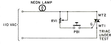
SIMPLE TRIAC TESTER
A triac, often used in lamp dimmers, interfaces, and AC control circuits, can't be checked directly with an ohmmeter like a diode. An ohmmeter would show a good triac as open or very high resistance between terminals MT1 and MT2; open or high resistance from the gate to MT2, and as two diodes in "reverse parallel" from the gate to MT1.
Therefore, those measurements would not show accurately whether a triac was open, shorted, or conducting properly.
In this simple circuit, closing PB1 applies gate current, set by Rv1. With Rv1 at minimum resistance, the triac should be fully on and the neon lamp lit brightly. With Rv1 set to maximum, the lamp will be very dim.
If the triac is open, the lamp will never come on and if it is shorted, the lamp will be fully lit even with PB1 open.
A standard incandescent bulb can be substituted for the neon lamp as long as its wattage doesn't exceed the power rating of the triac.
PARTS LIST FOR SIMPLE TRIAC TESTER
-110 Vac neon lamp Rv1-2M Ohm control pot PB1-normally open momentary pushbutton
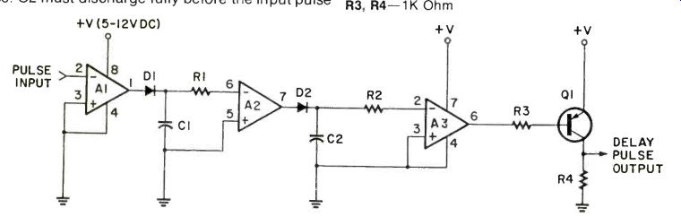
PULSE DELAY CIRCUIT
This circuit is useful for clock and digital applications. It can be used to delay a clock pulse by as much as one pulse width (or any part of one pulse). The output pulse can be no longer in duration than the spacing between input pulses.
The length of the delay and the pulse width are varied by changing the R1/C1 time constant. Op amplifier Al, half of a 1458 dual op amp, inverts the input pulse and charges up capacitor Cl. Time constant R1/C1 sets the Delay time. The slower capacitor C1 discharges, the longer the delay time will be, but it must discharge fully before the input pulse goes low.
Op amp A2 inverts the signal again, forming a narrow pulse whose width depends on time constant R1/C1. The output of A2 charges C2 to widen the pulse. C2 must discharge fully before the input pulse goes high again. Op-amp A3 squares off and inverts the widened pulse. The output of A3 is inverted, and is then delayed compared to the input signal.
Transistor Q1 inverts the output of A3, buffers it, and adjusts its level to (almost) the level of the power supply. Note that the input signal can be any voltage which is less than the supply voltage. Thus this circuit can also function as a level shifter.
PARTS LIST FOR PULSE DELAY CIRCUIT
A1, A2-1458 Dual Op-amp
A3-741 Op-amp
D1, D2-1 N914 Diodes
Q1-2N3906 PNP Transistor
C1, C2-0.1 of Capacitors
R1, R2-variable, try R1 = 27K, R2 = 22K Ohms
R3, R4-1K Ohm
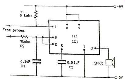
IN-CIRCUIT RESISTANCE VERIFIER
Simple low dc voltage audible testers are commonly used for checking the continuity of wiring, giving an audible indication of continuity. There are applications, however, where both low resistance paths (e.g. PCB tracks, transformer windings, etc) and high resistance paths (greater than a few kilo ohms) have to be verified. The circuit shown allows such paths to be checked using the well known 555 timer IC. Varying resistances applied across the test probes cause a resultant change in output frequency from the speaker.
PARTS LIST FOR IN-CIRCUIT RESISTANCE VERIFIER
IC1-555 Timer (any type)
R1-5K ohms
R2-3K ohms
C1-0.1uF C2-0.01 uF
SPKR-Miniature replacement speaker (any Type)
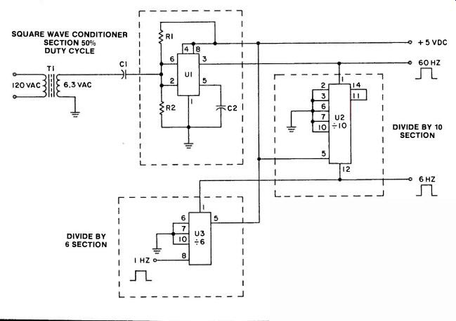
SQUARE WAVE CONDITIONER
Here is a circuit that is very simple to build but very effective and precise in its operation. The 1 Hz Square Wave Generator will fill the bill for every hobbyist or professional who needs a precision 1 Hz signal source.
Here is a circuit that is very simple to build but very effective and precise in its operation. The 1 Hz Square Wave Generator fill the bill for every hobbyist or professional who needs a precision 1 Hz signal source.
This circuit is compatible with TTL and CMOS. It is a square wave with a precise 50-50 duty cycle, whose accuracy is tied to the 110 VAC 60Hz household electrical system, close enough indeed to supply pulses for a clock. The beautiful part about it is that the 555 timer section is not operating as a divide by two but as a voltage divider, whose positive and negative cycle is very precise. The 60Hz output at pin #3 is fed to the 7490, which is set up as a divide by 10. This output, now 6Hz at pin #12, is fed to a 7492 set-up in the divide by 6 mode. The output of this stage is a perfect 1Hz square wave, suitable for any TTL of CMOS circuit needing a 1Hz signal.
This circuit is not entirely original. The author originally built a programmable up-down counter and clock, using the 74190, 7447 and 555. It was almost impossible to use a 555 time base that was not susceptible to ambient temperature changes. I needed a precise 1Hz square wave. Having a copy of Don Lancaster's TTL Cookbook, I found a circuit for a "single-ended power-line conditioner" but the duty cycle was not exactly 50%. However, the Bugbook Reference Series, by Howard Berlin, had exactly what I needed. I, therefore, combined the two circuits and...Voilla!!! A beautiful 1Hz generator with a perfect 50-50 duty cycle. Needless to say, my counter-clock works beautifully. I have timed it over an 8-hour period with a commercially sold Digital Clock and it kept time to the second. The uses for this circuit are far-reaching and almost endless. It is actually the same effect as a "Schmitt-Trigger". Here is how it works: In the "Square Wave Conditioner" section, the 555 is set up as "Schmitt Trigger". The two internal comparator inputs (pins #2 and #6) are tied together and externally biased at 1/2 Vcc, through R1 and R2. Since the upper comparator at pin #6 will trip at 2/3 Vcc and the lower comparator will trip at 1/3 Vcc. the bias provided by R1 and R2 is centered within these two thresholds.
A sine-wave input of sufficient amplitude to exceed the reference levels causes the internal flip-flop to alternately set and reset, producing a square wave output. As long as R1 equals R2, the 555 will automatically be biased for any supply voltage in the 5 to 15 volt range. A scope readout reveals that the square wave is out of phase with the 60Hz sine wave. However, by 180 degrees, which presents no problem at all. Hopefully, this "project" will help some hobbyists, especially beginners, along the road of "Digital Electronics".
PARTS LIST FOR SQUARE WAVE CONDITIONER
1HZ SQUARE WAVE GENERATOR
T1-120VAC/6.3 VAC 300 mA
C1-.01 mF MYLAR 16V
C2-.01 mF MYLAR 16V
R1-100K 1/4 W 5%
R2-100K 1/4 W 5%
U1-NE555 TIMER
U2-SN7490 DECADE COUNTER
U3-SN7492 BASE 12 COUNTER (All parts available from Radio Shack)
Also see: IC Testbench (xviii)
adapted from: Electronics Handbook 1992