By Hugh Gordon
All Bill wanted was to have a single extension speaker in his workshop. He decided to connect it to his stereo and reasoned that one channel would be enough. So, using a simple 'Y' connector, he tapped onto the rear of the left, channel speaker upstairs, fed the lead down through the floor and over to his bench. To the lead, he connected an old speaker he'd had around for years. Now, he could enjoy the music right where he worked.
But not for long. It came with the suddenness of switching off a lamp. The sound stopped. Not even a hint of static could be heard from his extension speaker. Bill ran upstairs to check the stereo. The left channel was dead.
At the service shop, he nearly cried as the technician told him with a voice of doom, "The large scale integrated circuit that drives the left channel is burnt out. It'll cost you about eighty dollars." What caused such a catastrophe? Bill had severely mismatched the impedance on that channel.
Attention must be paid to matching impedance.
When properly matched, two things happen:
1. Maximum power is delivered to the load, which, in this case, was a speaker or a set of speakers.
2. The optimum design current flows through the output transistors whether they are discrete or included in an IC.
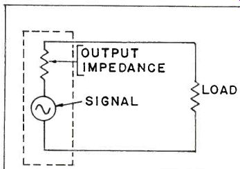
FIG. 1
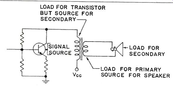
FIG. 2
Changing load impedance that upsets the matching can produce different results, depending upon the design of the final output stage. Sometimes people create a mismatch and get away with it. Then, they tell a friend. Result: their friend may have a sudden surprise.
Let's examine the effect of changing load impedance from its design value.
All sources driving a load have an internal resistance or impedance, expressed in ohms. A simple and familiar source is a dry cell or battery. It has an internal resistance, which is a result of the electrode materials and the chemicals used. It's very small, but you can observe its effect. As the cell ages, its internal resistance increases. This is observable in a flashlight when the lamp becomes dim as the battery ages.
A transistor amplifier stage also has internal ‘resistance', although when dealing with AC signals, it is referred to as impedance. In Figure 1, the simplified equivalent circuit of an output transistor is shown within the dotted lines. The output impedance indicates the opposition to the AC signal between the emitter and collector. The load shown with a resistor symbol, represents the speaker.
Impedance is defined as the total opposition to AC current flow offered by a device or circuit at a particular frequency. Impedance is a combination of resistance, inductive reactance and capacitive reactance, and is analyzed using phasors or vectors and complex Math. Since impedance is frequency sensitive, it varies as frequency changes.
Amplifier stages have both an input and output impedance. With load or impedance matching of an amplifier to speaker, the output impedance is the important factor.
There are two basic output amplifier designs, and each exhibits its own impedance matching characteristics.
One design uses a transformer to couple the output stage to the speaker, while the other uses no transformer but couples either directly or through a large value capacitor to the speaker.
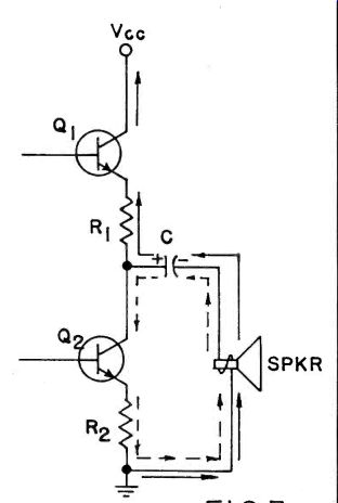
FIG.3
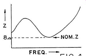
FIG.4
The transformer-coupled stage is not as common as it once was but is still seen in older car radios, portable radios and public address systems. A simplified schematic is shown in Figure 2. This is single-ended, but the reaction to a load impedance is similar to the push-pull design.
The transistor is the source of the signal while the speaker is the final load. The transformer couples the transistor to the speaker as well as matching the different impedances.
The primary of the transformer is the load for the signal source (or transistor), while the secondary acts not only as the load for the primary but the signal source for the speaker. The speaker, then, is the load for the secondary windings.
To be properly matched, the impedance of the primary windings should be the same as the output impedance of the transistor and the impedance of the secondary windings should be the same as the rated impedance of the speaker.
How is this accomplished? Well, it's really up to the designer, but a brief explanation here will help you understand the process. You must be aware, however, that for simplicity, transformer efficiency, which is a result of its various AC losses, is not being considered. We'll leave that up to the engineers designing the equipment.
Recall the formula: Np/Ns = √(Zp/Zs) ? Sometimes it is expressed as (&)2 = iP. In this formula, Np/Ns is the turns ratio of the transformer and Zp/Zs is the impedance ratio required of the transformer.
Now, if the output impedance of the transistor is 1000 ohms and the speaker impedance is only 8 ohms, the match is obtained by application of the formula. Inserting the values above for the impedances, where Zp is the transistor output impedance and Zs is the speaker impedance, we have:
Np/Ns = √(Zp/Zs) = √(1000/8)=√(125)=11.2
This tells us that the turns ratio of the transformer, neglecting losses, should be 11.2 to 1 for a proper match. Or, that the primary windings should have 11.2 times as many turns as the secondary. Although we have ignored the various losses that would be considered by a design engineer, you can see the approach.
Using a transformer which can handle the currents involved and which has the correct turns ratio will properly match the output transistor's impedance with the speaker impedance.
The second circuit is the common transformerless type which gives superior sound reproduction, especially if no capacitor is included in the output circuit. A typical transformerless circuit which includes the coupling capacitor is shown in Figure 3.
The coupling capacitor has been included to simplify the explanation of the circuit. Here, transistors Q1 and Q2 are connected in the common-collector configuration to provide the low output impedance needed to match the speaker.
These two transistors work together to supply a signal to the speaker. The inputs to Q1 and Q2 are 180 degrees out of phase so that as Q1 is conducting, Q2 is either cut off or almost cut off. To reduce crossover distortion, the output transistors are usually operated with a small amount of bias current which flows continuously.
When a positive-going signals is applied to Q1, a negative-going signal is applied to Q2. This causes Q2 to be cut off while Q1 conducts. The signal current then flows in the path shown by the solid arrows--from ground, up through the speaker, C1, R1, and Q1, charging C1 in the process to the polarity shown.
When the signal reverses, and Q2 is positive-going, Q2 will conduct, while Q1 is cut off. The signal current now will flow in the direction of the dotted lines, from C1, through Q2, R2 and the speaker.
Thus, both halves of the signal are produced.
Speakers are rated at a nominal value of impedance, expressed in ohms, with typical common values being 4 and 8 ohms. However, because a speaker reacts somewhat as an inductor, where impedance varies with frequency, the actual impedance of the speaker may often be three to five times its nominal value, and seldom is exactly 4 or 8 ohms.
Figure 4 illustrates a typical graph of speaker impedance vs frequency. The nominal impedance chosen by the manufacturer is usually at the low dip in the graph. This curve can effectively be flattened by good speaker cabinet design and a proper crossover network.
Nevertheless, all amplifiers should be terminated with a speaker of the correct nominal impedance. To vary far from this value could have disastrous results.
There are two types of mismatch and each has a different effect. Mismatching by connecting a lower than recommended load impedance would imply that you have either connected a speaker with too low an impedance or perhaps paralleled speakers. For example: connecting two 8-ohm speakers in parallel produces a total of 4-ohms, and connecting this combination to an 8-ohm, tap on your amplifier, mismatches downwards.
Should you lower the impedance with a transformer-coupled amplifier, Figure 2, the impedance of the output transformer primary windings is also lowered because of the reflection of impedance through the transformer. This has the effect of decreasing the AC signal voltage seen across the primary windings and hence also across the collector-emitter of the transistor. Power output to the speaker is reduced.
Should the load impedance be reduced to the extreme value of zero ohms, there will, of course, be no output.
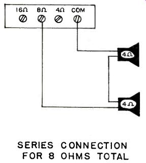
SERIES CONNECTION FOR 8 OHMS TOTAL FIG.5
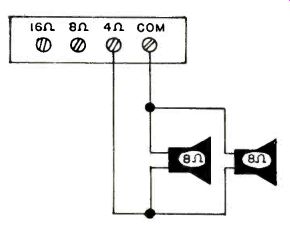
PARALLEL CONNECTION FOR 4 OHMS TOTAL FIG. 6
The other type of mismatch is when you increase the load impedance above the design value. If you do that in the transformer-coupled circuit, the impedance of the transformer primary increases. Then, the AC signal voltage across the primary as well as across the transistor also increases, even though the power output to the speaker again decreases. It may even be possible, in some circuits, for the signal voltage across the transistor to reach a value large enough to damage the output transistor, especially if the speaker was disconnected and the set turned on.
In some older car radios that use a transformer-coupled output, a shorting speaker jack is used. Pull the speaker plug and the transformer secondary is shorted, effectively providing a load impedance of zero ohms, thus protecting the output stage should the set be turned on with the speaker disconnected.
Impedance mismatching in a transformerless circuit has just the opposite effect. Lowering the impedance of the speaker will result in an appreciable increase in collector current. The output transistor(or transistors) has a low output impedance, in the order of about 8 ohms, and, with an 8-ohm speaker in series with it, the total impedance seen by the signal is 16 ohms. Now, should you reduce the speaker impedance to 4 ohms, the total impedance drops to just 12 ohms, a change of 25%. As the collector current increases, the power dissipation in the transistor also increases, for power is proportional to the square of the current. Double the current and power dissipation increases by four times! This extra power can sometimes generate so much heat that the poor overworked transistor or IC quickly burns out. Unless, of course, it's your lucky day and the fuse goes first.
Should you increase total impedance in the transformerless circuit, all you do is effectively lower the collector current and the speaker power output, but there will normally be no damage to a well-designed output circuit.
Should you still want to connect a load impedance that differs from its design value, here are two rules for you to follow:
1. Transformer-coupled amplifier: never increase the load impedance.
2. Transformerless or direct-coupled amplifier: never decrease load impedance.
However, it is more advisable to try to match the impedances as closely as possible. In many instances you won't know what type of amplifier output stage is in your set. Don't chance guessing. It could be like playing a game of Russian Roulette. Although some of you may have connected speakers in such a way that opposes the rules above and had no nasty surprises, you're probably reaping the benefits of good design by an engineer who included a large safety factor.
If you really must connect multiple speakers to a system that is not designed for these additions, try to connect them in such a way, series, parallel, or series-parallel, so the sum of the impedance equals the value needed for that amplifier.
Figures 5, 6 and 7 show three possible multiple speaker arrangements. There are many more. Be aware, however, that power delivered from the amplifier divides between the speakers proportionately to their individual impedance. For example: assuming 20 watts is delivered from the amplifier, then each speaker in Figure 5 or 6 would receive 10 watts and those in Figure 7 only 5 watts.
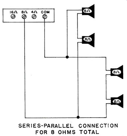
Figure 7--SERIES-PARALLEL CONNECTION FOR 8 OHMS TOTAL
Also see: Power Supply Basics
adapted from: Electronics Handbook 1992