By Steve Sokolowski
Power supplies have been an intricate part of electronics products since the first electron tube was invented in the 1800's but very few authors have taken the time to tackle the seemingly complex chore of explaining just how to convert a large AC voltage into a form that is more palatable to the more conventional electronic components used in today's super computers, space shuttles and let's not forget the tiny LCD televisions that can easily fit into a shirt pocket.
No matter what the nature of your project, some sort of outside energy is needed to excite microscopic particles called electrons, more affectionately called "Little Joe Electron" by my high school electronics teacher (Mr. G.E. Brown). By applying a force, Little Joe will either be attracted or repelled by the source of energy. With enough Little Joes' flowing from the negative to the positive supply, an electrical current is said to be present. This current is measured in Amperes. (Amp, milli-Amps, micro-Amps). The more electrons flowing within a conducting medium with the least amount of resistance, the higher the current.
If enough force is present within a conducting path of little or no resistance, another form of energy is created. This secondary energy is called HEAT. And heat IS AN ENEMY to delicate electronic components. To control the obvious destruction of parts, we must have some means of governing the amount of energy created by an electronic circuit. This circuit is called a "Power Supply" and power supplies are what this feature is all about.
Power Supply Basics
In broad terms, a power supply is a circuit that takes the normally available AC (alternating current) household line voltage and transforms it into a DC (direct current) voltage usually of a lower value (if working with transistorized circuits). Power suppliers are the "silent partners" of all electronic projects. Every circuit requires some sort of "energy" to fulfill its intended function. The power supply does just that.
A Typical Power Supply
A power supply is a circuit that can come in a variety of sizes and shapes. From a small 5 volt' Amp unit to devices that can deliver voltages in excess of tens of thousands of volts with a deadly current of 100 Amps or more. No matter how complex the supply is, it can be broken down into five functional blocks: The AC input, the transformer, the rectifier, the filter and the regulator. Figure 1 illustrates a typical power supply in a form called a block diagram. For any power supply to function, we need a primary voltage source. Here, this voltage can be obtained from the standard household AC outlet. Due to differences in wiring and your location within the United States, this voltage can range anywhere from 105 to 125 volts.
Even with this 20 volt variation, a power supply can operate efficiently as long as the input voltage remains at some reasonable value. If the input AC voltage drops too low, the supply might not be able to sustain its rated DC output voltage and current to the load (electronic circuit).
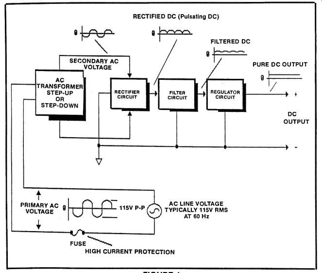
FIGURE 1
Conversely, if the AC input voltage is too high, the power supply will produce an output DC voltage that is higher than needed. Subsequently, this higher voltage can easily destroy electronic parts because the suggested operating voltage has been exceeded.
At the primary AC voltage input line, you will notice a device called a "fuse." A fuse is a component that is placed in series with one side of the input AC voltage line. Here any excessive flow of "Little Joe" Electrons caused by a short circuit placed across the load will generate heat as mentioned above. This heat will literally melt a small fine wire located within the fuse at a predetermined current. Hence, if the fuse "opens", all AC voltage flow will be abruptly halted and power to the circuit will be broken until the fuse is replaced.
Fuses have the unhealthy reputation of being thrown away after each and every high current surge.
One way to save a few dollars and to provide maximum protection to the circuit, is to replace the standard fuses with a device called a "circuit breaker." These components are basic switches that will automatically open with the presence of excessive current flow. If we take a look inside a circuit breaker, we will see a "trip sensor" connected in series with the breaker's switch. As long as the current flow is well within the rated value of the breaker, the internal switch will remain closed. Thus providing a path for electrons to flow, If, on the other hand, the current flow exceeds the rated value, the trip sensor will open the breaker's contacts, thus disrupting the flow of current. The breaker's contacts will remain open until an outside force (your finger) re-sets the sensor.
Once re-set, the circuit breaker will, again, silently protect your valuable investment until the next surge of unwanted high current.
Transformers
A transformer is a device that converts the high AC voltage into an even higher or lower AC voltage. By using the principle of "magnetic coupling", NO direct connection is made between the input and output voltage. A transformer of this type can be called an "Isolation Transformer." The AC input voltage (placed on the transformer's PRIMARY windings) is isolated from the usually lower AC output voltage (secondary winding), thus preventing a deadly shock hazard.
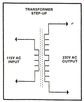
FIGURE 2
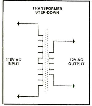
FIGURE 3
For a transformer to make use of the phenomenon called magnetic or inductive coupling, a varying voltage, like the one found in an AC voltage must be placed on the primary winding of the device. Here the voltage swing from positive 57V to negative 57 volts creates strong magnetic fields. It is this field that induces an alternating current in the secondary winding of the transformer. Just how strong this induced voltage is depends on the number of copper wire turns in the windings. If the number of turns on the secondary of the transformer is greater than the number in the primary windings, the inductive coupling will induce a voltage that is GREATER than that found in the primary. This transformer is said to be a "STEP-UP" transformer (See Figure 2). If the number of wire turns in the secondary is LESS than that found in the primary, the induced voltage will be LESS than that in the primary. This transformer is said to be a "STEP-DOWN" transformer (See Figure 3). If the number of turns in the primary is equal in number to the secondary, the voltage at the secondary will be equal to the primary. What good is this? This transformer isolates the deadly AC primary voltage from the secondary. Remember earlier, we mentioned "Isolation Transformers?" Well, this is how it is accomplished. Figure 4 illustrates the electronic schematic of an "Isolation Transformer."
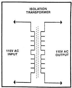
FIGURE 4
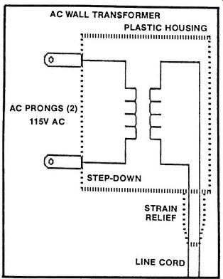
FIGURE 5
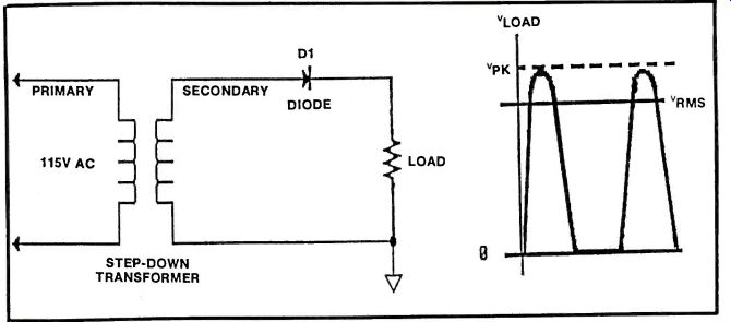
FIGURE 6
Since the novice electronics hobbyist may have limited knowledge relating to transformers and the potential dangers of wiring an AC line cord, we strongly recommend making use of a device that does away with all the potential dangers of using line transformers. These devices are called "Wall Transformers" (See Figure 5). Wall transformers are step-down transformers that are completely encapsulated in plastic with only two connections showing.
One being a twin lead wire where the lower secondary voltage is delivered. And the second is the familiar AC male prongs. By using a device such as this, the potential danger that might be encountered in wiring a line transformer is eliminated. Also, all soldered connections on the primary and secondary windings are protected by the plastic cover, thus eliminating the shock hazard associated with standard board mounted transformers.
Wall transformers come in a variety of output voltages and current ratings. Depending on the amount of current required, pricing of these devices also vary widely. Surplus electronic suppliers sell wall transformers for as little as $1.95. Surely, your safety is worth $1.95? We think it is. Make use of Wall Transformers wherever possible.
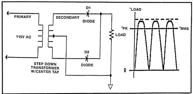
FIGURE 7
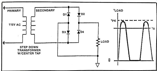
FIGURE 8
Rectifiers
After the AC input voltage is brought down to a lower level by a step-down wall transformer, the next step is to somehow convert the AC voltage into a raw form of DC (Direct Current) signal. Even though the voltage output of the rectifier varies greatly, the polarity of the signal remains the same. Thus the term "pulsating DC." Stages of rectification are often composed of semiconductor diode networks or solid state bridge rectifiers. There are three basic classifications of rectifier circuits used in power supplies. The HALF WAVE (Figure 6), the FULL WAVE (Figure 7) and the BRIDGE shown in Figure 8.
The simplest of the three is the Half wave rectifier since the circuit requires only one diode and no center tap on the transformers secondary winding.
The principal disadvantage of the half wave rectifier is that only one half of the available secondary voltage is rectified. Rectifying only half of the signal produces gaps in the output voltage (See accompanying wave form at Figure 9). These gaps produce an output voltage that has a lower average value and a higher amount of AC ripple riding at the output. With a high AC ripple content at the output, heavier filtering will be required, thus increasing its overall cost. Because of the high ripple content, Half wave rectifiers will not be found in commercial power supplies.
Full wave rectifiers provide a significant advantage over its predecessor (See Figure 7). With the wiring arrangement as shown in Figure 7, two diodes are used instead of one. Two diodes are allowed to conduct on BOTH halves of the secondary AC signal.
The resultant waveform can be seen in Figure 7. As you can see, the number of DC pulses has been increased by a factor of two. With almost no time delay between the conduction of the first and second diode, the AC ripple content of the output is greatly reduced. Also, a power supply using the full wave configuration can provide a steadier DC voltage output and it can also support heavier loads. The main drawback of using the full wave is the use of the center-tapped transformer. This circuit requires a ground reference point and it is provided by the center tap.
Constructing center-tapped transformers is an expensive proposition, and its cost is a reflection of its manufacturing complexities. Even the price of wall-mounted transformers, making use of center taps, are quite expensive. So, for our needs, let's skip full-wave rectifiers and go right to the last classification of rectifiers; the "Bridge." By focusing your attention on Figure 8, you can see that the bridge rectifier provides, not only full wave rectification of the secondary AC voltage, but it also furnishes its own ground reference without the need of an expensive center-tapped transformer. The FULL secondary AC voltage applied to the bridge will appear as pulsating DC at its output. As an example, if an AC signal of 12 volts is applied to the bridge, you can expect an output of a pulsating 12 volts. Bridge rectifiers are the choice of equipment designers. You can find them in the more expensive unregulated power supplies and in almost all types of regulated supplies.
When choosing rectifiers of any power supply design, two important factors must be considered; the forward current and the peak inverse voltage (it used to be called Peak Reverse Voltage PRV). The forward current is the maximum current that can flow through the diode in its forward biased (conducting state) direction without causing harm. This forward current value of the device should be equal to the maximum expected load plus another 50% for safety sake. Many circuits that you will be building will, without a doubt, operate well under 1 Amp. To provide a pulsating DC output with a current under 1 A, the 1N4401 diode is my choice. With a PIV (Peak Inverse Voltage) rating of a whooping 500V at 1 Amp, the 1N4001 diode will perform in virtually any power supply circuit that you can think of. And best of all, the diode can be purchased for about $.02 each.
Filters
Filter capacitors used in power supplies have the function to smooth out the pulsating DC signal to a somewhat steady DC output. Even with heavy capacitor filtering, the effects of AC ripple can still be seen in the output. Even with a capacitor with a value in excess of 1500uf (1500 micro farads) can not eliminate all the undesired ripple associated with any of the three rectifier classifications. Basically, a filter capacitor is an energy storage device that will charge to the peak voltage rating of the pulsating DC. Then, in the absence of an applied voltage, will discharge slowly to provide energy to the load. The amount of discharge depends on two factors. The first being the physical size and the amount of current drawn by the load. If the circuit requires a large amount of current, the capacitor will discharge more rapidly than if the circuit used less current. This heavy current use causes a large amount of AC ripple to appear at the output of the supply (See Figure 9). A lighter load, obviously, will draw less current, resulting in a much lower ripple content. To provide substantial filtering of the pulsating DC, capacitors are often wired to the output in parallel. This will, in effect, double the surface area of the capacitor plates, increasing its capacitance. For example, a filter capacitor needed for a supply must have a value of 3000uf (3000 micro farads). If two 1500uf capacitors were placed in parallel, the effective capacitor value would be 3000uf. Adding capacitors in parallel to achieve as pure a DC voltage as possible has its drawbacks.
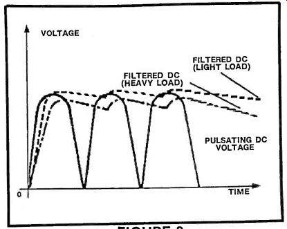
FIGURE 9
Capacitors in the range of 1500 to 3000uf are relatively large in size. And the larger the capacitor, the higher the price tag. Using capacitors with a value of 10,000uf or more can become dangerous. As mentioned earlier, capacitors are energy storage devices. Even if the power is disconnected from a capacitor of this size, electrical energy IS STILL PRESENT. This energy potential can easily create serious shock hazards to the user. To reduce the possible shock risk, a high value resistor called a "bleeder resistor" should be added in parallel to the filter capacitor. A 1 to 2 meg ohm (1,000,000 to 2,000,000 ohm)resistor is used to bleed the excess electrical energy stored by a charged capacitor, to ground, helping to eliminate any shocking experience.
Choosing a capacitor to be used as a filter, select a capacitor with a working voltage that is about 50% above the peak voltage that will be encountered by the component. For example, say a bridge rectifier delivers a pulsating DC of 12V, the filter capacitor should be rated on or about 15 volts. Higher voltage capacitors can also be used without any adverse effects on circuit performance.
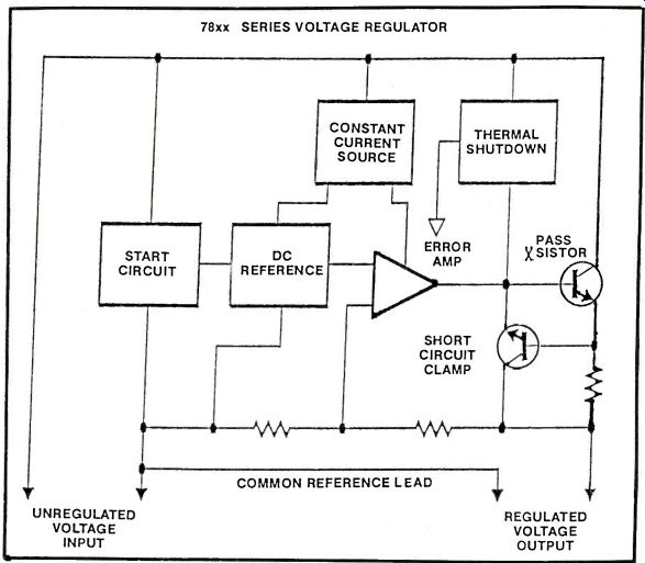
FIGURE 11
Ripple voltage can be measured by placing an AC voltmeter across the now filtered DC output. The voltage can be read directly in volts. In a well designed and filtered power supply, the ripple should not exceed 0.1% of the input AC voltage.
At this stage, the output of our imaginary power supply is called UNREGULATED. For driving lamps, solenoids and relays, unregulated power supplies, will handle the job quite well but when it comes to powering amplifiers or computer circuitry, unregulated voltages will create havoc, from producing an annoying AC hum in amplifiers to developing unwanted pulses on computer Data Busses.
Unregulated power supplies should not be considered. For well regulated, inexpensive power supplies, manufacturers have developed miniature circuits that provide a pure DC output over a wide range of voltages. These devices, as you might have guessed, are called Voltage Regulators.
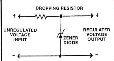
FIGURE 10
Regulators Voltage regulators are devices that allow a precise control and adjustment of the DC voltage output. By adding an inexpensive regulator to a power supply's output, AC ripple can be almost completely eliminated. Enough so that the output can be considered to be equal to the DC output of a standard 9 volt transistor radio battery.
This simplest form of voltage regulator is the Zener diode with a current limiting resistor in series. as shown in Figure 10. The unregulated voltage from the output of a filter is delivered to the resistor-Zener circuit. Often called a "clamping" circuit. As with any electronic component, Zener diodes come in a variety of voltage and current ratings. For a particular voltage output, any Zener diode with a rating less than the unregulated input voltage can be used in the design.
The series resistor will dissipate the extra voltage and help reduce the unregulated voltage to the desired level. The value of this resistor depends on the voltage drop across it. This drop can be considered to be the difference between the unregulated voltage and the regulated voltage desired (Zener diode voltage). Also, the current required by the circuit must be taken into consideration. For example, let's take an unregulated 12V power supply. We need this circuit to be reduced to 10 volts. With this example, the series resistor must be able to withstand a voltage drop of 2 volts across it.
If the maximum load current is to be 1 Amp, then by using Ohms law, the value of the resistor has to be 2 volts/1 amp or 2 ohms. The power dissipated by the resistor is also related to the amount of current drawn by the circuit. In this example, the power dissipated by the series resistor will be (1 amp x 1 amp) x (2 ohms) or current squared, times resistance. We come up with an answer of 2 ( Watts). By addling a safety factor of 50% to the wattage value we just calculated, the Zener's series resistor should be 2 ohms with a wattage rating of 3 Watts.
As with any electronic component or circuit, there are drawbacks. If the load were to be disconnected, the full load current would be impressed across the Zener, blowing it out. Zeners don't cost that much but accidental removal of the load should not place any component in a position of over-stress or inevitable destruction. To eliminate this, let's take a look at integrated circuit type voltage regulators.
IC Regulators
Integrated circuit voltage regulators, such as those in the 7800 and the 7900 series family are excellent alternatives to Zener circuits. Internal regulator circuitry compares the output voltage to an internal reference (See Figure 11). Any difference between the two will create an error voltage that causes the current flow of the IC to change at the output transistor. By making use of this scheme, the error amplifier keeps track of all output loads across the IC and then makes the appropriate corrective action to keep the output voltage at a constant level.
Voltage drops and loading current are also important in the choice of IC voltage regulators. The unregulated input voltage must exceed the regulated DC output by several volts if IC regulators are to function properly.
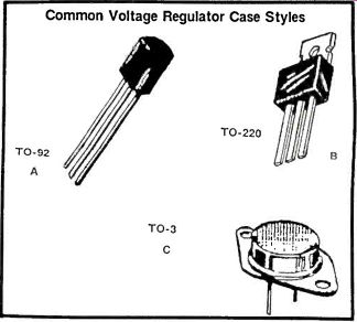
FIGURE 12
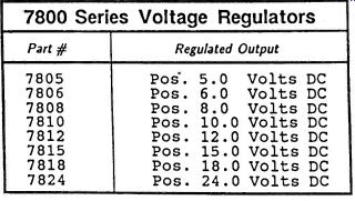
Table 1 7800 Series Voltage Regulators
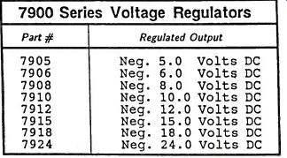
Table 2 7900 Series Voltage Regulators
Table 1 and 2 list a number of IC Voltage Regulators. These devices can be easily purchased in any Radio Shack or mail order electronic house at a surprisingly small cost. Depending on the type and manufacturing procedure used, IC voltage regulators can withstand currents from as little as 100mA to as much as 5 amps. A dead giveaway to the current handling capability of an IC voltage regulator is its case style. Figure 12 illustrates the three most commonly used regulators on the market. Figure 12A shows a regulator in a TO-92 configuration. This TO-92 case style is similar to a small three lead plastic transistor. Its small size reflects that it can supply only small 100mA currents to the load. On the other hand, Figure 12B shows a regulator in the larger TO-220 case. When used with the appropriate heat sinking capabilities, the TO-220 can deliver currents up to 1A, with 500mA the more typical current output. Finally, Figure 12C shows the ever popular diamond shape of the TO-3 regulator. Regulators of this type can deliver up to and exceeding 5A of continuous current. But for the hobbyist, TO-3's delivering 1.5A will more than satisfy your needs.
Negative Voltage Output
Once a transformer, rectifier, filter and regulator are assembled to form a single output regulated power supply, several other features can be added to make the circuit more versatile. For example, sometimes you may need a power supply to deliver a Negative voltage rather than the standard positive. The polarity of the power supply is determined by the rectified network. If the diodes in all of the rectifier circuits that we have discussed were reversed, the normal positive voltage would be inverted to a negative output. Also note that the filter capacitor(s) must be reversed.
Otherwise the capacitors will heat up and literally explode. In a negative voltage power supply, the now reversed diodes will pass the negative half of the secondary AC voltage. The output, will produce a negative pulsating DC signal with negative AC ripple.
Figure 13A shows a typical positive power supply using a half wave rectifier for simplicity. The output of D1 is filtered by C1 with the results regulated by a 7800 series voltage regulator. Figure 13B shows how to convert the circuit in 13A to deliver a negative output. Note that, in this case, D1 is reversed. This feeds negative voltage to filter C3, which is also reversed. The only abnormal thing about this circuit is that we use an IC regulator from the 7900 series of IC chips. Any regulator with the starting number 79xx will deliver an output of negative voltage, while a 78xx number will deliver an output of positive voltage. The last two numbers determine the output voltage of the device. Both the 7800 and the 7900 regulators are basically the same, except for output polarity.
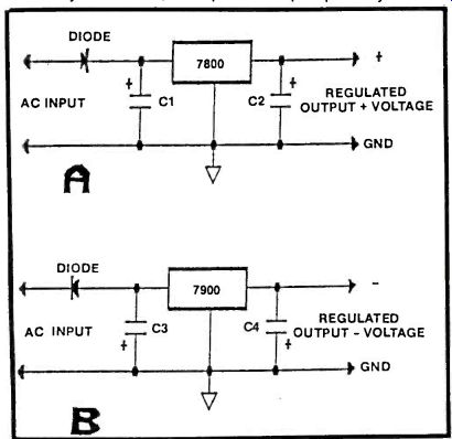
FIGURE 13
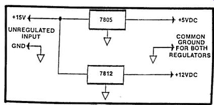
FIGURE 14
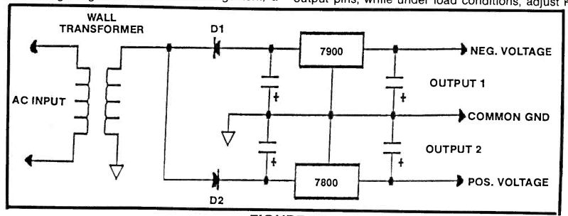
FIGURE 15
Multiple Voltage Outputs
There will be times that a circuit design requires two or more different voltages. A second output voltage can easily be added to a power supply by tapping into the filtered DC to provide an unregulated voltage for the second regulator. Figure 14 depicts a simple multi-output power supply. Here, a common unregulated voltage is filtered by the usual capacitor. From here, the voltage splits up into two branches. Branch one feeds a voltage to the input of a 7805 positive voltage regulator, while the other voltage is branched to the input of the 7812 regulator. At the outputs, the 7805 will deliver a regulated +5 volts, while the 7812 will output a regulated +12 volts. To provide a multiple output, the filtered DC output must be higher than the highest desired regulated output.
For supplies requiring both a negative and positive output, the circuit in Figure 15 can be considered. By using a half wave rectifier, D1 will pass the negative half of the secondary AC voltage, while D2 will pass only the positive half. Since D1 delivers a negative voltage, filter capacitors C1 and Q2 must be connected to the circuit to reflect this polarity. Note that the negative terminals of both C1 and C2 are connected to the 7900 voltage regulator. Capacitors C3 and C4 are fed a positive voltage from D2 so the positive terminals are both connected to the 7800 series voltage regulator. With this arrangement, a negative voltage determined by the 7900 IC used will be present at output 1, while a positive voltage, again determined by the 7800 IC used, will be present at output 2. As stated before, the input pulsating DC voltage must be at least 2 volts higher than the highest output regulated voltage.
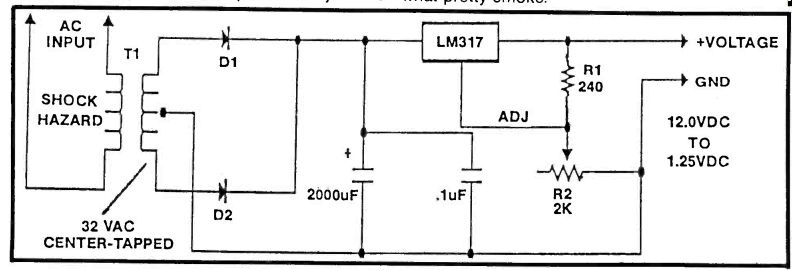
FIGURE 16
Variable Voltage Regulators
So far, we've discussed voltage regulators with a fixed output voltage level. Variable voltage regulators also exist. The LM317 is an example of an adjustable power regulator that is ideally suited for variable supplies. Figure 16 is a schematic of an adjustable power supply using the common LM317 regulator.
The ADJ or the center pin is connected to a voltage divider network formed by R1 and potentiometer R2.
As the value of R2 increases, the reference voltage on the ADJ pin also rises, this in turn, will raise the output voltage. The output voltage from the LM317 can be varied from 1.25 volts up to the limit set by the value of R2. For the proper values of the components used in Figure 16, check the regulator's application notes for the equations you'll need to determine the values.
Voltages below 1.25V can not be obtained because of the minimum voltage required across R1 to maintain the correct bias that the LM317 needs for normal operation.
The LM317 comes in the TO-3 diamond shape case style and it was designed to deliver upwards of 1.5 amps of load current. Due to its high current potential, a TO-3 type heat sink is highly recommended.
To use, just connect a voltmeter across the two output pins, while under load conditions, adjust R2 until the desired voltage level is indicated on the meter. For the novice electronics hobbyist, it is a good idea to get into the habit, when connecting any project to an adjustable power supply, to adjust the potentiometer voltage output down to 0V, or in the case of the LM317, to read 1.25V on the meter. It would be one heck of a mistake if you connect a project designed to operate at 5 volts, to a power supply that has been adjusted to 30 or more volts. Oh! what pretty smoke.
Also see: Don't Gamble With Impedance Mismatch
adapted from: Electronics Handbook 1992