Reading about electronics can be fun and instructive, but the only way to become a knowledgeable technician is to get hands-on experience, by actually connecting resistors and capacitors together in circuits that do something. These circuits can be as simple as turning a light on or off, or making some kind of alarm sound. As long as we have a power source and a load connected together by wires, we have a functioning circuit.
Another way to think about circuits is to consider one part the input, and another part the output. This is notably true of amplifiers. The circuits in the following Circuit Fragments section are like this; they all Do something.
These projects are comparatively simple--and each uses fewer parts than those in our Workbench Projects and IC Testbench sections. If you study them and put several together you will increase your understanding of how all electronic components and circuits work.
SWL'S SUPER SIGNAL BOOSTER
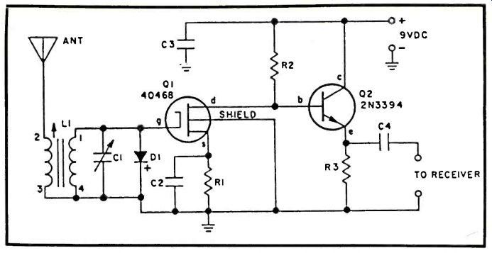
Super sensitivity is the feature of this two-transistor shortwave preselector. It provides overall gain as high as 40 dB from 3.5-30 MHz.
Diode D1 protects against excess gate voltage caused by nearby transmitters, while Q1 serves as an emitter follower to match the medium output impedance of the FET transistor to the low input impedance of the receiver.
Since Q1 is a MOSFET type with a gate that's very sensitive to static changes, Q1 must be handled with a short-circuit across all leads until just before power is applied. Also, a soldering iron must not be applied to Q1's leads unless they are shorted.
L1's connections are specified in the instructions supplied with the coil. A short length of RG-174U coaxial cable should serve as the connection between the preselector output and the receiver with which the unit is to be used.
PARTS LIST FOR SWL'S SUPER SIGNAL BOOSTER
C1--365-pF tuning capacitor
C2, C3-0.05-uF, 25-VDC capacitor
C4-470-pF, 25-VDC capacitor
D1-1 N914 diode
L1--Antenna coil: 1.7-5.5 KHz
use Miller B-5495A, 5.5-15 MHz
use Miller C-5495A, 12-36 MHz
use Miller D-5495A
Q1-RCA 40468 FET transistor (Do not substitute)
Q2-2N3394 npn transistor
R1-470-ohm, 1/4-watt resistor
R2-2400-ohm, 1/2-watt resistor
R3-4700-ohm, 1/4-watt resistor
-----------SWL's SUPER SIGNAL BOOSTER
LIQUID LEVEL DETECTOR
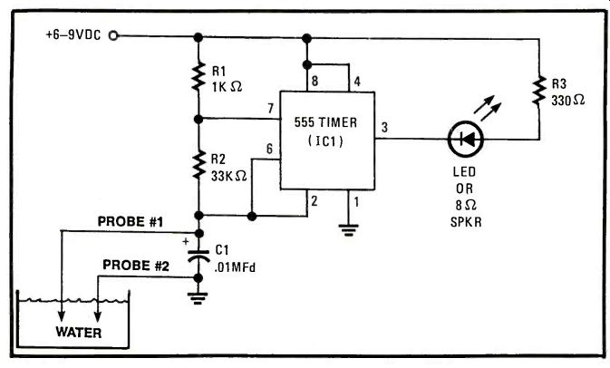
This circuit was designed to alert the automobile owner when the fluid container for the windshield wiper container was nearing empty, at which point it will light an LED diode, strategically placed on or near the dashboard for convenient observation.
If you like sound better than visual indicators, you can substitute an 8 ohm speaker in place of the LED. All that is required for this adjustment is to remove the LED and connect one lead of the speaker to pin #3 of the IC chip and connect the other lead of the speaker to ground. Be sure that the 330 ohm resistor is still connected to pin #3 to complete the circuit.
While this circuit is designed primarily to alert you when the liquid is low in your windshield wiper container, it can be applied to numerous other liquid containers. Let your imagination take over.
PARTS LIST FOR LIQUID LEVEL DETECTOR
C1--.01 Mfd Disc capacitor
IC1--555 timer (Integrated Circuit)
LED--light emitting diode or 8 ohm speaker
R1-1K ohm resistor, 1/4 watt
R2-33K ohm resistor, 1/4 watt
R3-330 ohm resistor, 1/4 watt- 6 to 9 VDC power supply
NEGATIVE POWER SUPPLY
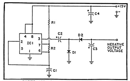
Many operational amplifiers operate from a dual-polarity power supply. For low current applications, it may be easier to construct this negative power supply using one IC, rather than rectifying from the power line or transformer. IC1 operates in an astable mode with essentially square wave output at pin 3. C2, C3, D1 and D2 form a full-wave voltage doubler circuit which produces approximately minus 14 volts with no load at the negative output terminal. The circuit will deliver 12 volts into a load of 1000 ohms.
PARTS LIST FOR NEGATIVE POWER SUPPLY
IC1-555 timer R1-1,000-ohm, 1-watt resistor R2-10,000-ohm, 1/4-watt resistor C1--.01-uF ceramic capacitor, 15 VDC C2, C3, C4-15-uF electrolytic capacitor, 25 VDC D1, D2-1N4148 diode
TOUCH CONTROL
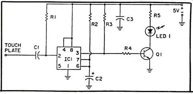
Have you ever been in an office building where the elevator up-down buttons aren't switches at all, but work by touch? You can build a similar touch control circuit using a 555 timer IC. The circuit shown operates an LED, but you can easily modify it to control a doorbell or any other device. IC1 is connected as a one shot or monostable multivibrator with the trigger input, pin 2, wired to a high-impedance network. When the input terminal is touched by a finger, stray AC voltage pickup is impressed upon pin 2 of IC1, causing it to trigger. This causes pin 3 to go positive and provides forward bias to C1 which illuminates the LED. R2 and C2 determine the time interval that LED 1 is illuminated, and for the values shown is about 3 seconds. The circuit is not fussy about power supply voltage.
PARTS LIST FOR TOUCH CONTROL
C1-0.01-uF ceramic capacitor, 15 VDC
C2-1.0-uF electrolytic capacitor, 15 VDC
C3-0.1-uF ceramic capacitor, 15 VDC
IC1-555 timer
LED1--large LED
Q1-2N4401
R1-10,000,000-ohm, 1/2-watt resistor
R2-4,700,000-ohm, 1/4-watt resistor
R3, R4-4,700-ohm, 1/2-watt resistors
R5-470-ohm, 1/2-watt resistor
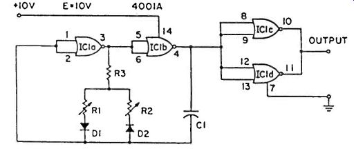
BASIC PULSE MAKER
Need a basic square-wave generator for all those digital projects? This quad NOR gate 4001A CMOS chip which can be easily obtained, stands ready to do the job with great simplicity. Note the two pots, R1 and R2. These govern both frequency and duty-cycle (symmetry), via diodes D1 and D2. C1 determines the overall frequency range. A C1 value of 0.1 uF, produces a range of about 11 to 2500 Hz. Using a 0.2 uF value, the range is about 4 to 700 Hz. The remaining two gates (pins 8-13) act as buffers, to isolate the oscillator from the effects of circuit loading. Duty cycles of almost 10 to 1 can be obtained.
PARTS LIST FOR BASIC PULSE MAKER
C1--0.1-uF capacitor for 11-to-2500 Hz range, 0.2 uF capacitor for 4-to-700 Hz range
D1, D2-1 N4148 diode
IC1-4001 A quad NOR gate R1, R2-500,000-ohm linear-taper potentiometer R3-1000-ohm resistor
TELEPHONE VOICE
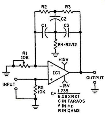
The "telephone voice" effect is usually created by passing a voice signal from a high quality microphone through a bandpass amplifier--a device that attenuates the frequencies on both sides of a selected frequency. Bandpass amplifiers are also effective at providing mid frequency boost--presence, as it's called in hi-fi terms.
The center frequency of this bandpass amplifier is determined by the values of C1, C2, C3, R2, R3, and R4. The exact frequency can be determined from the formula shown. To start, assign a value of 100,000 ohms to R2 and R3 (use 1/2-watt resistors). To avoid hum pickup, the unit should be assembled in a metal cabinet. Potentiometer R1 serves as the Q-control; it determines the degree of boost at the center frequency.
R5 connects to the non-inverting ( +) input of the IC, R1 between ground and the inverting (-) input. No pin connections are given because the IC is available in many different configurations.
Of course, you could find a carbon microphone "button" and matching transformer to create the effect naturally, but that's not how it's done in the big city, bub!
PARTS LIST FOR TELEPHONE VOICE
C1, C2, C3--(C1 equals C2 equals C3, see formula)
IC1-Type 741 opamp
R1-10,000-ohm pot
R2, R3-(R2 equals R3, see text)
R4-R4 = R2/12 R5-10,000-ohm, 1/4-watt resistor
adapted from: Electronics Handbook Vol. X