Integrated Circuits, digital and linear, are where it is at; that is, the state-of-the-art in electronics technology. For the newcomer to this fascinating area of electronics, we have tried to select a representative cross-section of the digital and linear integrated circuits available on the market, and design construction projects around them that not only entertain, but educate as well.
In truth, there is no easy way to learn electronic theory, at least in a manner that will prepare the individual to cope effectively with the influx of technical applications that are now reaching the home, the car, and your place of business. For those with no prior experience in the construction of electronic projects, we strongly suggest that you begin with some of the Transistor projects found elsewhere (Circuit Fragments) in this magazine. By beginning with these simpler projects, where construction technique is less critical, you will learn, by necessity, the basics of component arrangement, lead trimming or lead dress as it is properly called, and the difficult art of translating those funny lines and squiggles on a schematic diagram into a working piece of electronic equipment.
For those of you who have had experience in building transistor projects before, the word is caution. Integrated Circuits are extremely sensitive devices and require very special handling.
THE WAVESHAPER
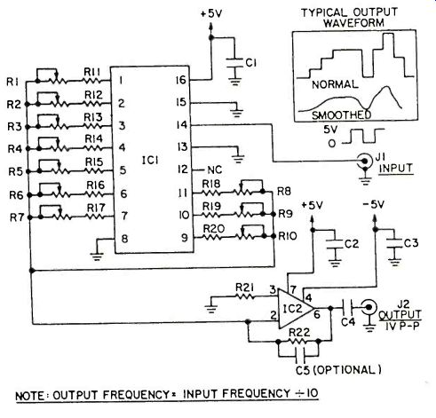
This little circuit illustrates the principle behind multi-kilobuck laboratory-style waveform synthesizers as well as some of the more advanced music synthesizers. Into J1 you should feed a square-wave signal swinging from ground to almost 5-volts. The input signal's frequency should be ten times that of the desired output. Adjusting potentiometers R1 through R10 will enable you to literally design the shape of the output waveform. If you can get hold of an oscilloscope, use it to observe the effect of R1 through R10 on the output. At the same time, feed the output to an audio amp so that you can hear the changes in timbre that occur as the waveshape is altered. Capacitor C5 can be used to smooth out the chunky shape of the output. With a 10 kHz input, start with a value of 0.1 uF for C5 and experiment. Make sure at least one potentiometer is set to maximum resistance and that at least one is set to minimum.
This guarantees a full 1-volt peak-to-peak output.
PARTS LIST FOR THE WAVESHAPER
C1, C2, C3-0.01-uF ceramic disc capacitor, 35 VDC
C4--0.5-uF mylar capacitor, 35 VDC C5-see text
IC1-4017 CMOS decade counter
IC2-741 op amp
J1, J2-phono jack
R1 through R10--2-megohm linear-taper potentiometer
R11 through R20--68K-ohm 1/2-watt resistor, 10%
R21, R22-15K-ohm 1/2-watt resistor, 10%
A SWITCH WITH A MEMORY
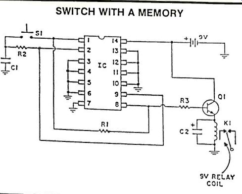
Here is a switch with unlimited uses. When momentary contact switch S1 is pressed, the relay will be energized. Press S1 again and the relay will be de-energized. In other words, this circuit remembers what state it was in even after S1 is released. This type of circuit can be very handy around the house. All unused pins should be grounded.
PARTS LIST FOR SWITCH WITH A MEMORY
C1--0.1-uF ceramic disc capacitor, 15 VDC
C2-1-uF electrolytic capacitor, 15 VDC IC1-4069 hex inverter
K1-Relay 6-9 VDC, 500 ohm coil, Radio Shack #275-005
Q1-2N4401
R1, R3-10,000-ohm, 1-watt resistor
R2-91,000-ohm, 1/2-watt resistor
S1-SPST momentary-contact pushbutton switch
CODE PRACTICE OSCILLATOR
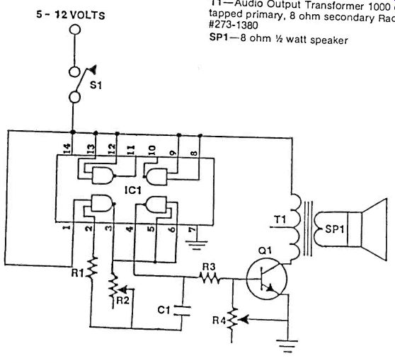
If you are an Amateur Radio Operator or just want to learn Morse Code, a code practice oscillator can be an invaluable tool. The code Practice oscillator is simple to build, requires only a few parts, and operates over a wide voltage range.
Two of the gates of the 4011 Quad NAND Gate are used to make a simple oscillator, whose frequency can be changed by adjusting R2. R4 is used to control the volume of the oscillator and Q1 drives speaker SP1.
PARTS LIST FOR CODE PRACTICE OSCILLATOR
C1--0.001uf Capacitor
IC1--4011 CMOS Quad 2-input NAND Gate
R1--1,500,000 ohm, 1/4 Watt Resistor
R2--1,000,000 or 2,000,000 ohm
Potentiometer R3- 10,000 ohm 1/4.
Watt Resistor R4-5000 ohm
Audio Taper Potentiometer
Q1--2N3903 NPN Transistor or Equivalent
S1-Code Practice Key
T1-Audio Output Transformer 1000 ohm center tapped primary, 8 ohm secondary Radio Shack #273-1380 SP1-8 ohm 1/4 watt speaker
DOUBLE FEATURE
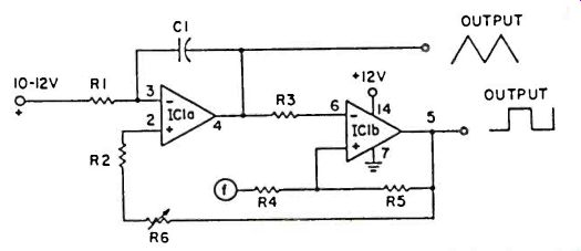
The versatile quad op amp LM-3900 (or MC-3401) can easily be persuaded to deliver two different waveforms from two of its sections, reserving the other two for mixing or amplification purposes.
Section one is an integrator, furnishing a fine triangular waveform, the other unit supplies a square wave signal. Adjusting R6 varies both frequency and duty-cycle (symmetry) of the two waveforms. AC1 value of 0.001 uF will give a frequency of about 1 kHz while 0.01 uF will be close to 100 Hz.
PARTS LIST FOR DOUBLE FEATURE
C1-0.001 or 0.01-uF ceramic capacitor
IC1-LM-3900 or MC-3401 op amp
R1, R4--1,000,000-ohm, 1/2-watt resistor
R2, R3- 100,000-ohm, 1/2-watt resistor R5--120,000-ohm, 1/2-watt resistor R6-500,000-ohm, linear-taper potentiometer
AUTOMATIC TURNOFF
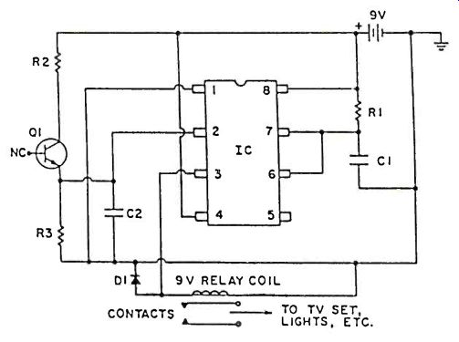
This circuit can save you steps, time, and electricity. When you leave a room and turn out the lights, for example, this circuit will sense that the lights are off and will activate the relay coil. Use it to turn off the TV, hi-fi, or another light in another room without bothering with extra house wiring. Or you can use the circuit to help keep burglars away. With 01 sitting at the window, it will turn on house lights when the sun goes down. R1 and C1 keep the relay in operation for a minimum of one-half second to avoid bouncing of the relay contacts.
PARTS LIST FOR AUTOMATIC TURN OFF
C1, C2--0.01uF ceramic disc capacitor
D1--1N914 or 1N4148
IC1--555 timer
Q1--NPN phototransistor FPT100 or Equivalent.
R1--4,700,000 ohm, 1/4 watt resistor
R2, R3--1,000,000 ohm, 1/4 watt resistor
Relay-6-9 VDC coil with switch contacts rated at 120 VAC /2 amp
HOME INTERCOM SYSTEM
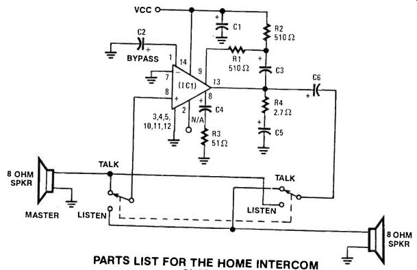
This circuit requires a little more than average skill in construction. Therefore, it is advisable that the experimenter or hobbyist have some experience with integrated circuits and /or solid state devices before attempting construction of this circuit. A breadboard is recommended for the final construction as a permanent device for home use. IC's are extremely sensitive so proceed with caution.
PARTS LIST FOR THE HOME INTERCOM SYSTEM
C1-0.1 Mfd disc capacitor
C2--Any available capacitor
C3--4.7 Mfd disc capacitor
C4--25Mfd disc capacitor
C5--.05Mfd disc capacitor
C6--100Mfd disc capacitor
SPKR IC1--#388 1.5W
Audio Power Amp
R1, R2-510 ohm resistors
R3-51 ohm resistor
R4-2.7 ohm resistor
S1, S2-SPDT single pole/double throw switches
Vcc-see instructions for Max. Vcc on IC package Misc-two 8 ohm speakers
MAG TAPE AMP
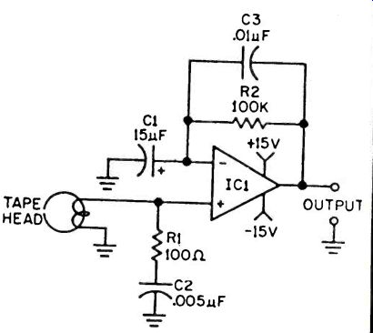
From time to time surplus dealers offer complete tape or cassette mechanisms-everything ready-to- go except for the electronics, and at rock- bottom prices of $10, $15 or $20. Often, all the mechanism needs is this equalized tape head preamplifier.
Though the power supply is rated at ±15 VDC, almost optimum results will be obtained with supply voltages as low as ±7 VDC. Two ordinary 9-volt transistor radio batteries will power the preamp for many hours.
As with all these projects, the 741 IC is internally compensated and no special wiring practices are needed; the preamp can be built in just about any enclosure.
PARTS LIST FOR MAG TAPE AMP
C1--22-uF electrolytic capacitor, 25-VDC or better
C2--0.005-uF disc capacitor, 25 VDC or better
C3--0.01-uF capacitor, 25-VDC or better
IC1--Type 741 opamp
R1--100-ohms, 1/2-watt resistor
R2--100,000-ohms, 1/2-watt resistor
---------------------
EVEN ODDS
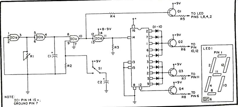
The continued versatility of the 4017 counter and DL-750 digital display is demonstrated in this Odd-Even or Coin Toss simulator. As an added feature, the decimal point of the display is illuminated for an Odd or Even "Low Count," 0, 1, 2, 3, or 4 count from the counter. Even numbered counts (0 is considered even, for the sake of symmetry) cause the display to present an E, while odd-numbered counts result in a 0. Segments A, D, E and F are common to both 0 and E, but they are driven by the clock along with B, C, and G to stimulate all the segments into "random" motion.
Holding down the pushbutton, causes C to discharge through R, giving an uncertainty period of five or seven seconds, depending upon the size of the capacitor chosen.
Good Luck!
PARTS LIST FOR EVEN ODDS
C1-0.47 to 2.2-uF electrolytic capacitor, 15 VDC C2-50 to 100-uF electrolytic capacitor, 15 VDC D1 through D10-1N4148 diodes IC1-4017 decade counter
Q1 through Q4-2N4401 transistors LED 1-DL-750 7-segment common cathode display or equivalent R1-500,000-ohm, 1/2-watt resistor R2-100,000-ohm, 1/2-watt resistor R3-1,000-ohm, 1/2-watt resistor R4-560-ohm, 1/2-watt resistor R5, R6, R7, R8-1,000-ohm, 1/2-watt resistors S1-SPDT momentary-contact pushbutton switch
----------------------
PROGRAMMED MUSIC
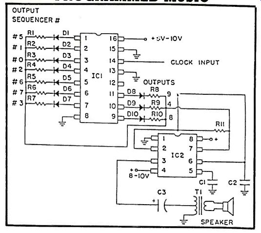
"Music" may be a little optimistic, but sequential tones are entirely possible with this circuit, and with a little experience, simple but recognizable themes can be produced. The system combines the 4017 decimal decoder counter with the 555 timer in astable oscillation. As the counter steps through its ten outputs, a different frequency-determining resistor (R1-10, which may range from 1 K-100K) is activated, through an isolation diode. The input clock frequency may be 1 and 5 Hz; use slower tempos for chime-like notes for an electronic door-bell. Notes may be made longer by giving succeeding steps, like 5 and 6, the same value tuning resistors. Rhythm may be accomplished by skipping one or more outputs. For very short themes, the next stage can be made to reset the counter. Composition, anyone?
PARTS LIST FOR PROGRAMMED MUSIC
C1, C2-0.1-uF ceramic capacitors, 15 VDC
C3-1,000-uF electrolytic capacitor, 25 VDC
D1 through D10--1N4148 diodes
IC1-4017 decade counter
IC2-555 timer R1 through R10-1,000 to 100,000-ohm, 1-watt resistors (see text)
R11--4,700-ohm, 1-watt resistor
SPKR--8-ohm PM type speaker
T1-audio output transformer 1000-ohm center-tapped primary/8-ohm secondary (Radio Shack #273-1380 or equivalent)
-------------
TWO TONE ALARM
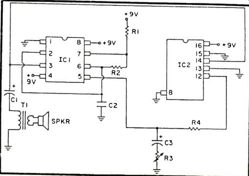
When this circuit is triggered into action, it is hard to ignore for very long! A 555 timer is operated in the astable free-running mode, with its output powering booth a loudspeaker and clocking a 4017 counter. Pin 12 of the counter provides a high-low output which changes with every five input pulses counted. This output is applied via a resistor of from 2.2K to 10K ohms to pin 5, the modulated input of the timer. This produces a strident warble that calls immediate attention. More mellow, but interesting, tones can be obtained with the addition of the RC filter shown.
PARTS LIST FOR TWO TONE ALARM
C1--100-uF electrolytic capacitor, 25 VDC
C2--0.1-uF ceramic capacitor, 15 VDC
C3--1-uF electrolytic capacitor, 25 VDC
IC1--555 timer IC2-4017 decade counter
R1, R2-4,700-ohm, 1/2-watt resistors
R3--10,000-ohm linear-taper potentiometer
R4--2,200 to 10,000-ohm, 1-watt resistor (see text)
SPKR--8-ohm PM type speaker
T1--audio output transformer 1000-ohm center-tapped primary / 8-ohm secondary (Radio Shack #273-1380 or equivalent)
Also see: Testing and Replacing Integrated Circuits
adapted from: Electronics Handbook Vol. X