POWER ADAPTER UPGRADE
Power adapters commonly used for powering calculators come in a variety of useful DC voltages (3, 6, 9, 12 volts typically). Cassette recorders, portable radios, etc., often are powered by 4 (1.5) volt batteries i.e. a total of 6 volts. These low cost adapters are excellent potential sources for powering cassette recorders, where the heavy current drain from the motor soon drains the batteries. In their original form, however, power adapters are inadequate for the following reasons:
1. The actual output voltage will depend upon the load connected. An, as labeled, 9V adapter such as the Radio Shack (273-1455), will measure several volts above 9 volts, depending upon the impedance of the meter used to measure the voltage.
2. For use with radios, there is often discernible hum from the speaker.
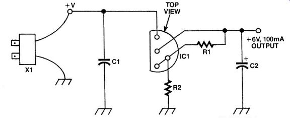
We, therefore, need to provide an upgrade. The circuit shown here uses a three terminal regulator (IC1), to provide an accurate 6 volts output. The output is controlled by R2. R1 is part of the regulator design requirements. Capacitor C1 is also part of the required design.
Capacitor C2, a large electrolytic, on the output smooths away most of the annoying hum. Changes in load resistance are controlled by IC1 so the output is constant irrespective of the load. The value of R2 is that measured across a variable resistor, after a 6 volt output has been obtained. The value is not critical-any value of R2 to give an output voltage of 5.8V to 6.2V is satisfactory.
100mA of output current can be supplied from the IC shown. For most applications, this is quite adequate.
Other adapters can also be used. The output stability is excellent!
PARTS LIST FOR THE POWER ADAPTER UPGRADE
IC1-LM317 3 terminal adjustable regulator
R1--21 0 ohm resistor
R2-745 ohm resistor (for 6 volt output)
C1--0.1 microfarad capacitor
C2-1000uF/35 volt capacitor
X1--9 volt adapter (Radio Shack 273-1455 or similar)
-------------------------
HOBBY MOTOR SPEED CONTROL
These days, there are plenty of small high-speed drills that can be run from a small power supply. This little project gives much greater control to your drill at low speeds and uses pulse width modulation.
If you've ever made your own printed circuit boards, then you'll know how handy a little hobby drill can be.
These are used to drill the 1 mm holes that the components fit through onto the board. The great thing is that they only require 12VDC at currents of 1 amp or so this in a package which fits easily into the palm of your hand.
However, as with all motors, they don't run particularly well at low speeds when you're trying to line up the bit or do that special job. The speed can jump around all over the place and make the task almost impossible.
This little circuit uses a technique called Pulse Width Modulation and does it all using just one IC and a few other components. Let's take a look and see how it all works.
Circuit Diagram
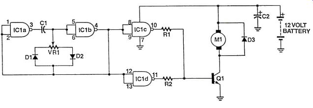
IC1 is a CMOS 4011 quad NAND gate IC with IC1a and IC1b connected as a variable-pulse-width oscillator. The frequency of this oscillator is set by VR1 and C1 while VR1 sets the pulse width.
Looking at this section of the circuit in more detail, diode D1 restricts flow by redirecting it so that the capacitor can be charged and discharged at rates set by VR1, which sets the pulse width.
By pulse width, we are talking about the ratio of time the output is high to the time that it is low. If the output is high for only half the time, the average DC voltage is half the supply. If the output is high for only 25% of the time, then the average DC voltage is only a quarter of the supply.
When VR1 is turned so that the wiper is closest to D1, the pulse width will be at its minimum and when it is closest to D2, the pulse width will be at its maximum.
The subsequent signal from the output of IC1 b is coupled to IC1c and IC1d which are coupled in parallel to increase the current output. This circuit arrangement is valid so long as the two gates being paralleled perform the same function.
The outputs at pins 10 and 11 feed resistors R1 and R2, which in turn drive transistor Q1 and turn the motor on and off at varying rates. Although the frequency remains the same, it is the pulse width or 'duty cycle' which sets the speed of the motor. The thing is that the motor cannot respond as quickly to the on-off-on-off power that is applied and instead, integrates or averages out the power being applied.
The benefit though is at low speeds the motor will no longer stall since the pulses of power will still give the motor enough torque to turn, albeit slowly. Diode D3 protects transistor Q1 from negative voltage spikes which are produced by the motor's coil. Capacitor C2 supplies the circuit with decoupling and stabilizes the speed circuitry.
This controller can be built into a small box where the rotary control of VR1 can be put on the front panel within easy reach of the drill. It shouldn't be used for motors that pull more than 2 amps of current and Q1 should be mounted on a small heatsink if the current consumption goes beyond 1 amp.
PARTS LIST FOR THE HOBBY MOTOR SPEED CONTROL
C1-0.1 uF, mylar, capacitor
D1, D2--1 N4148, small signal, silicon, diode
D3--1N4004, rectifier, diode
IC1--CMOS, 4011 IC
M1-12VDC, motor, (PCB drill etc.)
C2--470uF, 16VW, electrolytic, capacitor
D1-BD679, NPN, Darlington, transistor
R1, R2-1.5k12, 1/4W, 5%, resistor
--------------------
HEADS or TAILS
Have you ever been stuck trying to make a decision between something you have to do and something else you'd prefer to do? Well, here's your chance to blame your decision on a small piece of electronics! In days gone by, the easy way to make a decision was to just toss a coin yet it was never too hard to make the coin land on the side you wanted--by cheating.
Now you can make the decision as close to random as you can get with this tiny circuit. It uses two low-cost CMOS ICs and a few other components—what’s more, you can have it up and running in just a couple of hours.
It will also help to explain how logic circuits work and you can learn quite a bit about digital logic just by building this simple project. Let's take a look at the circuit diagram.
Circuit Diagram
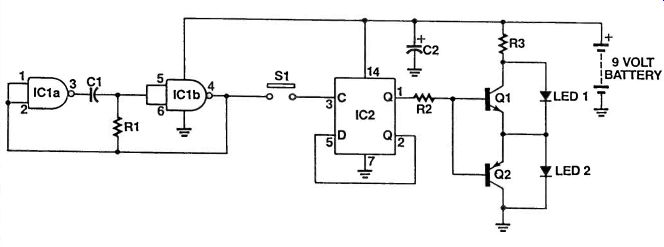
IC1 is a CMOS 4011 quad NAND IC. IC1,a and b are connected to form a squarewave oscillator which runs as soon as the power is applied.
IC2a is one part of a CMOS 4013 dual-D flip flop IC which is connected in a toggle mode. What we mean by `toggle' mode is that on each incoming clock pulse, the Q output goes alternately high and low. This is achieved by connecting the Q-bar output back into the D input.
The Q-output at pin 1 is connected via resistor R2 to two complementary NPN/PNP transistors which are connected in parallel with two LEDs, LED 1 and 2.
When the Q-output is high, Q1 turns on, since it is an NPN device, which shorts out LED 1 and allows LED 2 to light. When the Q-output goes low, the reverse happens: 02 turns on, shorting out LED 2 and lighting up LED 1.
When switch S1 is pressed, it couples the square-wave signal from the output of IC1 b into the clock input of IC2a. While it is pressed, the flip flop will be toggling so quickly that it will appear that both LEDs are on all of the time but this is not true. Because our eyes cannot respond quickly to flashing light, it just appears as though they are on continuously.
When you release the button, the toggling will stop as the clock signal is removed. Depending on the state of the flip flop, either of the two LEDs will be lit up and it is impossible to say which since the clock frequency is so high, around 1kHz. The push button should be a momentary-on type.
The project can be run off anything from 6 to 12V but I suggest a 9V battery is as convenient as anything else.
PARTS LIST FOR HEADS OR TAILS
C1--0.01 uF, mylar, capacitor
C2-100uF, 16VW, electrolytic, capacitor R1, R2--10kí2, 114W, 5%, resistor R3-68052, 1/4W, 5%, resistor IC1-CMOS, 4011, IC IC2-CMOS, 4013, IC Q1-BC548, NPN, transistor Q2-BC558, PNP, transistor S1-SPST, momentary, switch LED 1, 2-5mm, red, LED
By Darren Yates
-------------------------------
BATTERY OPERATED TOUCH LAMP
Have you seen those 'magic lamps' that turn on and off as soon as you touch them? Well, now you can make your own touch lamp that runs off batteries using only one IC and a handful of other components.
There's no doubt about it. Touch lamps are convenient! You don't have to go fumbling around for a tiny switch somewhere. All you have to do is touch the base of the lamp and it's either on or off as you please! You can make your own entirely safe battery operated model, which can be used in the car or caravan using only a handful of components in only a couple of hours. Let's take a look and see how the Touch Lamp circuit works.
Circuit Diagram
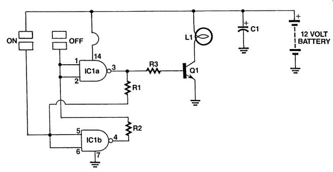
As you can see, the circuit uses two NAND gates from a CMOS 4011 quad NAND gate IC, a few resistors and a couple of other components.
IC1 a and IC1 b are cross connected to form what's called a 'flip flop'. It may sound like a funny name, but the Flip Flop is a basic memory element. If you have a computer, then there may be thousands, maybe even millions of these inside.
Also connected to the inputs of the two gates are two touch pads. They can be made out of thin sheets of aluminum, or even a small piece of perfboard. You need two sets of these-one for the ON switch and one for the OFF switch.
Make sure that these pads don't touch each other, otherwise the circuit will trigger.
What happens is that if you now touch your finger between the two pads of the ON switch, this pulls the inputs of IC1 b high. This forces the output of IC1 a high, while holding the output of IC1b and the inputs of IC1a low. The high output of IC1 a now turns on transistor Q1 which switches on the light.
What we've done is to flip the circuit into one state.
Now let's look at what happens when we touch the OFF pads. This causes the exact same thing to occur but in the opposite direction. The inputs of IC1 a are now pulled high, which forces its output low as well as the inputs of IC1b. The output of IC1b goes high and keeps the circuit flopped back into the OFF state.
The low output of IC1 a now switches Q1 and the light OFF. This circuit is very reliable and will last indefinitely, if built well. Since, unlike a switch, there are no moving parts in this circuit, there is very little chance of anything breaking, except maybe the light but that goes without saying.
You can power the circuit from any 12V battery but under no circumstance should you ever connect this circuit up to your household power supply.
PARTS LIST FOR BATTERY OPERATED TOUCH LAMP
C1--470uF, 16vw, electrolytic capacitor
IC1-CMOS 4011
IC Q1-BD679, NPN, Darlington, transistor
L1-12V, 400mA, (approx.) Globe
R1, R2-10 m-o, 1/4W, 5%, resistors R3-2.2 K-o, 1/4W, 5%, resistor
------------------------------------------
AN UNUSUAL OSCILLATOR
Here's a circuit you're unlikely to see very often. It's a square wave oscillator generating signals in the audio frequency range, but uses the LM386 audio power amplifier rather than the 555 timer chip. Apart from its rarity, it has a distinct advantage over the 555 circuit. This circuit will drive a low impedance 8 ohm load directly! It is after all, the audio power amplifier, configured in a somewhat unusual mode. Try it and see--you'll be surprised that it's actually an oscillator and low frequency driver in the same design! What that means is that you can drive low impedance loads directly without going to the trouble of using an emitter follower of Darlington high current driver.
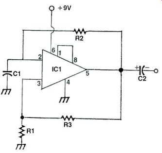
IC1 is of course the ever popular LM 386 audio power integrated circuit. The connections are fairly easy to follow. R1, R2 and R3 with C1 form the frequency controlling components. With the values shown the output frequency is around 1 kHz. All the components interact to some extent, hence the actual values are not too critical. C2 is the customary A.C. coupling capacitor feeding the signal to a low impedance load, e.g. 8 ohm speaker. Note pins 1 and 8 are linked. These are the normal gain control pins for the LM-386. Supply voltage can be the usual 9 volt battery.
Either of the feedback resistors i.e. R2 or R3 can be used as the prime controlling device, if you wish to keep the rest of the components fixed. In this way you can vary the frequency over a limited range. None of the values have been found to be too critical in practice.
PARTS LIST FOR THE UNUSUAL OSCILLATOR
IC1-LM 386 audio power integrated circuit
R1-1K ohm
R2-30K ohm resistor
R3-10K ohm resistor
C1-0.1uF capacitor
C2-50uF capacitor
-----------------------------------
ELECTRONIC METRONOME
If you're a musician and also a hobbyist then it's quite likely that music related circuits will be of particular interest to you, e.g. guitar amplifiers, fuzz units etc. For solo practicing a metronome is very useful for precise timing. The actual frequency of `clicks' is less critical than the regularity of the timing pulses. The circuit as shown here produces an appropriately tailored sound that is in `sympathy' with regular mechanical metronomes. The power supply is from a single 9 volt battery.
For adequate output levels, feed the metronome signal to an audio power amplifier, such as the LM386 or even directly into one of the auxiliary inputs of a guitar amplifier.
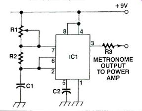
IC1 is the ever popular 555 timer chip, configured to produce a continuous stream of variable frequency pulses. To obtain the characteristic clicking sound of mechanical metronomes, the resistor values are chosen so that R1 is higher than R2. Additionally, R1 is made variable so that the beat rate can be adjusted to suit the tempo of music played. Capacitor (C1) is the final component for the timing section. The value is fairly high since the beat rate has to be relatively low, typically between 35 to 350 beats per minute is used for music purposes. The final components are C2, for decoupling and R3, for isolating the output.
For initial testing, you can connect a pair of high impedance headphones to the output from Pin 3, to find the best range of R1 that suits your music preferences.
Component values are not critical and can be varied to suit the circumstances.
PARTS LIST FOR THE ELECTRONIC METRONOME
IC1-555 timer integrated circuit
R1-1M potentiometer
R2-1K resistor
R3-1K resistor
C1--2 uF capacitor
C2--0.01 uF capacitor
-----------------------------------------------------
CAR BATTERY MONITOR
Have you ever gone out to the car on a cold winter's morning only to find that the battery is flat dead and you're going nowhere fast? Well, you need not worry about flat batteries anymore with this handy car battery monitor. It uses only one IC but gives you three clear levels of battery charge indication.
There's nothing worse than being caught with a dead battery and there's basically nothing you can do unless you carry a spare in the trunk. However, you can catch it before it happens if you look out for the warning signs.
When a battery is about to give its last, you'll notice that when you try and start your car, you'll notice that the starter motor will run quite slowly-yes, your car may still start because the starter motor represents a much bigger load on your car's battery than the spark plugs do.
This circuit monitors your car battery's voltage and lights up one of three LEDs depending on its voltage.
Let's take a look at how it works.
Circuit Diagram The first problem we have to overcome is the fact that if we want to use the car battery to measure itself, how do we do it? This is actually quite easy. By using a voltage regulator, we can obtain a steady DC voltage which, although lower than the battery voltage, is stable enough for us to use as a reference, which is what we need. In order to measure the battery, we need to compare it with a steady, accurate reference.
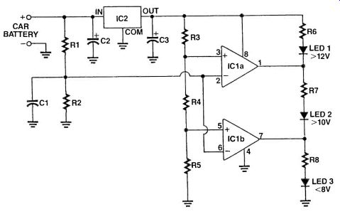
IC2 is a 7808 3-terminal regulator which produces a steady voltage of 8V. This provides our reference and also powers the rest of the circuitry.
The reference in our case is derived from just three resistors, R3, R4 and R5. The two tapoff points are fed into the non-inverting inputs of two opamps, IC1 a and b which form an LM358 dual package. The inverting inputs are joined together and fed with half of the battery voltage.
Note that the input resistor divider made from R1 and R2 are connected to the battery before the regulator so the tap off point between R1 and R2 is exactly half of whatever the battery voltage is; not what the regulator is. The job of the R1 /R2 resistor divider is to ensure that the input to the opamps doesn't rise any higher than the supply voltage, which in our case is 8V. This means that the car battery voltage would have to reach 16V. If this did happen, there would be something more seriously wrong with the car than just a "bad'' battery.
If the voltage on pins 2 and 6 is less than the voltage on pin 5 then LED 3 will light indicating that the battery voltage is below 8V. If the voltage on pins 2 and 6 is higher than pin 5 but lower than pin 3, then LED 2 lights up, indicating that the battery voltage is greater than 10V but less than 12V. If the voltage on pins 2 and 6 is higher than pin 3 then LED1 lights up, indicating that the battery voltage is higher than 12V. Construction of the Car Battery Monitor is not critical so long as you follow standard construction techniques. Vero-type or perfboard is more than adequate and you can also fit the project into a box and install it on your dashboard if you so wish. It's entirely up to you.
PARTS LIST FOR THE CAR BATTERY MONITOR
C1--0.1 uF, mylar capacitor
C2, 3--10uF, 25VW, electrolytic capacitors
IC1LM358, opamp IC
IC2-7808 8V, regulator
R1, R2-22 k-o, 114W, 5%, resistor
R3-3.9 k-o, 1/4W, 5%, resistor
R4-2.2 k-o, 1/4W, 5%, resistor
R5-10 k-o 1/4W, 5%, resistor
R6-R8-6809, 114W, 5%, resistor
LED 1-5mm, green LED
LED 2-5mm, yellow LED
LED 3-5mm, red LED
--------------------------
+++++++++++++++++++++++
Also see:
adapted from: Electronics Handbook XV (1994)