LED AUTO-NIGHT LIGHT

Night lights that you have to turn on and off manually are a pain. An automatic one is much more convenient, especially one with a source of light that lasts a long o time. The new high brightness LEDs are ideal for this purpose. Not only do they save on power usage, they also last much longer than incandescent lamps and are 110 easy to use.
Size is yet another advantage. This entire circuit fits easily on a board the size of a commemorative postage stamp.
Flexibility is still another advantage. The circuit can drive as many as 4 LEDs, each of which could be at a separate location as much as 20 feet apart.
For 2 LEDs, add the second one in series with X1.
Duplicate R5 and put either 1 LED or 2 in series with the resistor. The LED/resistor is connected in parallel with R5-X1.
C1 can be any value from 1 Mfd to 100 Mfd, all it must do is filter into a 3.7 Megohm load on standby and a 12K load actuated.
PARTS LIST FOR THE LED AUTO-NIGHTLIGHT
D1-1 N4007 Diode
Q1- Mpsa-42 Transistor
X1-High Brightness LED
C1-1-22Nfd, 160 WVDC, electrolytic capacitor
R1--3.7 Megohm, 1/4 watt resistor
R2, 3--100K Ohms resistors
R4-Photoresistive cell.
R5 -12K Ohm resistor, 1 Watt.
-------------
TEMPERATURE SENSING TRANSISTOR

A general purpose NPN transistor (Q1) can be connected as shown, to form a 2-terminal diode. In this mode, the transistor's output voltage will change as a function of temperature. The collector and base terminals are connected to ground and the signal is taken from the emitter. Resistor (R1) completes the divider chain, such that the voltage across the 'diode' decreases as the temperature rises. This small change in voltage can be amplified with a standard D.C. Op-Amp.
Typically, the D.C. output across the 'diode' changes by just over a millivolt for each degree "F" change in temperature.
PARTS LIST FOR THE TEMPERATURE SENSING TRANSISTOR
Q1-2N3904 general purpose NPN transistor, connected as a diode
R1-15K ohm resistor
----------------------
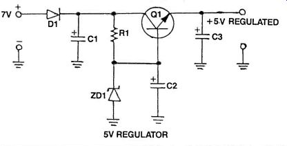
5V VOLTAGE REGULATOR
If you use a lot of TTL ICs, then you'll know the problems of running them. Because of their construction, they require a fairly exact 5V supply otherwise they will either not work or blow up.
Even though, these days, you can replace many TTL integrated circuits with CMOS versions, there are still many functions performed by TTL that have not as yet been copied into CMOS-they are too numerous to mention but you can make your own comparison.
The point is, if a 5VDC regulated supply is required for every project you build that uses TTL ICs, then your costs go up dramatically with the LM7805 regulator.
The circuit here uses only a few low-cost components and provides just about a perfect 5V supply with large amounts of supply decoupling using a little known but effective technique.
The circuit shown in Figure 1, also provides circuit protection, just in case you connect the supply the wrong way around the cause of many an IC destruction. This is provided by diode (D1). A diode will conduct a current as long as its anode is at a higher voltage than its cathode. Capacitor (C1) provides some initial supply bypassing.
The reason for this is to reduce the amount of AC ripple that may be present in the voltage. This can have mysterious effects on the operation of many digital ICs.
You may get states which don't agree with your circuit design and this will be a result of voltage supply ripple.
The voltage regulating is done by resistor (R1) and zener diode (ZD1). This is a 5.6V zener diode for reasons which will become apparent in a moment. The voltage at the cathode of the diode is very smooth.
This voltage is fed into the base of transistor (Q1). This is an NPN device which has a base-emitter voltage drop of 0.6V--the same as most other transistors.
This means that the voltage you get at the emitter is 0.6V less than that at the base. So if we had 5.6V originally, subtract 0.6V for the base drop and we get 5.0V at the emitter.
Because we are using the transistor in a buffer mode, we get a large current gain which allows us to drive up to 30 TTL ICs without worrying about the load current of the zener diode.
Capacitor (C3) provides some more bypassing to make sure that the power supply is squeaky clean. However, we haven't described the function of capacitor (C2). Capacitor (C2) has two functions. First, it provides bypassing for the zener diode to remove any noise, hum or ripple that may remain after the diode has done its work, and secondly it works in conjunction with transistor (Q1) to produce a "super capacitor". The transistor, in effect, multiplies the value of the capacitor by the gain or beta of the transistor. As an example if the gain of the transistor is 100 and the value of the capacitor (C2) is 10uF, then the effective bypassing capacitance at the output is 100 x 10uF or 1000uF. Simply, the more capacitance you have at the output, then the smoother the output voltage.
The transistor I have used here is a BD139 NPN power type, but you can use any typical NPN transistor that meets the power requirements of your circuit i.e.
the more TTL ICs you have to power with this circuit, the higher the power rating the transistor needs to have. You may also need to use a heat sink on the transistor if it gets too hot otherwise you may destroy it.
CONSTRUCTION
To start off, I recommend you build the circuit on a breadboard or some Veroboard so that you can see how the circuit works, then you can include it with any of your circuits where a fixed, regulated supply is required.
The main thing is that the input voltage must be at least 1 volt higher than the desired voltage and you can replace the 5.6V zener diode with one of another voltage for any voltage you require. Remember that the output voltage = V(zener diode) -0.6V.
PARTS LIST FOR THE VOLTAGE REGULATOR
C1-C3--100uF 16VW electrolytic capacitors
D1--1N4002 power diode
R1--470 ohm, 0.5W, 5% resistor
Q1--BD139 NPN power transistor or equivalent
ZD1--any 5.6V zener diode
Misc.-DC power supply, box, breadboard, wires, screws, nuts, washers etc.
-------------------------
CAR FUN BOX
Ever see one of those talking alarms? It tells you to stay away from the car it is protecting if you get too close.
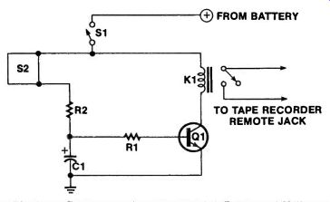
How about a device that mimics one of these alarms? Wouldn't it be fun to bug people with a "talking car?" The "Fun Box" consists of two parts; a tape recorder and a recorder control. A "shaker switch" is used by the control circuit in a normally open mode.
When the car is bumped, the power is applied through the shaker switch to C1, charging it through R2.
Transistor (Q1) turns on and stays on during the discharge of C1 through R1. This determines how long the tape will play.
K1 can turn on the Recorder with contact closure to the remote or by feeding power to the recorder. With a little imagination, you should have lots of fun with this device.
PARTS LIST FOR THE CAR FUN BOX
R1 -10K Ohms, 1/4 watt, resistor
R2-18 Ohms
C1-1000 Mfd, 35 WVDC capacitor
S1-Shaker switch or Mercury switch
Q1 -2N2222 transistor
K1-12 volt coil, SPDT contacts relay
------------------------------
TELEPHONE RING CONTROL
This device can be quite useful. When the telephone rings, it will turn on a light, activate a horn or whatever other device you so desire.
For a deaf person or someone with a hearing impairment, this device can flash a light for each phone ring, for people that have difficulty with their hearing, a horn or a bell.
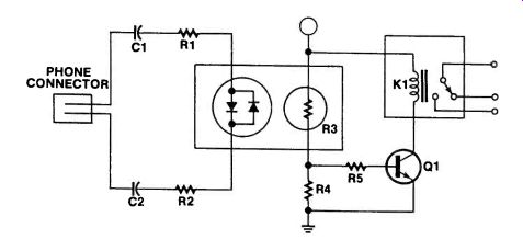
The circuit functions as a remote ringer control.
Operation is simple. The DC normally, present in the phone line, does nothing, since it will not pass through the capacitors. The AC ring voltage does pass through the capacitors, lighting the LED (X1). Resistance of the photocell (R3) lowers drastically, turning on transistor (Q1), which pulls in relay (K1). The power for this circuit is from a 9-12 volt supply.
You can power it from a battery but it would be best to power it from an AC power supply.
Be sure to tape the photocell to the LED with black tape to prevent a false actuation.
PARTS LIST FOR THE TELEPHONE RING CONTROL
R1, R2 -4.7K Ohm, 1/2 watt resistors
R3-Resistive photocell
R4, R5 -10K Ohms, 1/4 watt resistors
C1, C2-1.0 Mfd, 250 WVDC capacitors
Q1 -2N2222 Transistor
X1-Bicolor LED
K1-12 volt coil relay, 10 Amp contacts
-----------------------------
IN-LINE PHONE CHECKER
Here is a little device that will tell you whether or nor your phone line is OK and even indicate the ring power.
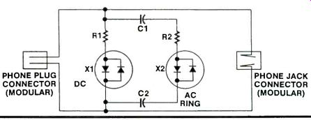
This device can remain connected to the line with a phone plugged into it so it doesn't tie upa plug while being tested.
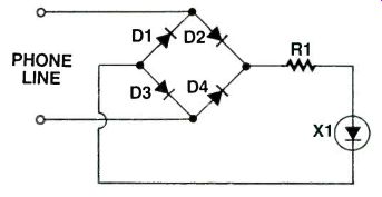
When the checker is plugged into the phone line, LED X1 indicates the presence of any polarity of the DC voltage on the line. Should the LED not light, check the phone line with a DC voltmeter. Absence of this DC voltage indicates that the phone line is dead.
When a call comes in, the AC ring voltage passes through C1 and C2 and lights LED X2. This ring voltage peaks at 220 volts so be careful around live phone lines.
This little device is powered by the phone lines and can be assembled on a board smaller than a credit card.
Now you can monitor your phone lines without fancy equipment.
PARTS LIST FOR IN -LINE PHONE CHECKER
R1 -27K Ohms, 1/2 watt resistor R2 -10K Ohms C1, C2-1.0 Mfd, 250 WVDC capacitors P1-Phone plug with short lead J1-Phone jack for modular plug X1, X2-Bicolor LEDs or Red 7 Green LEDs wired back to back
--------------------------
OK PHONE INDICATOR
You cannot tell just by looking at a telephone if it is functional. Looking at the phone line will not tell you if it is operational either. That is the job of the Phone OK Indicator. This little phone line powered device monitors the phone line and lights to indicate when the line is ready to use.
When a phone is off the hook for any reason, this devices' LED darkens. This indicates that someone is making a call or something is wrong with the telephone line. Mostly, this would serve as a phone busy indicator.
The diodes allow the indicator to be wired to the phone line either polarity and eliminates polarity worries.
Installation of a small unit like the phone OK indicator may be facilitated by making it plug into a modular phone jack, or hardwiring it in. Red and green are the wires normally in use for the phone. In multiline systems or when in doubt about which wires are correct, a phone or a meter should be used to check to determine which wires are right.
This device is capable of being constructed behind a small postage stamp, so it can fit even inside a phone, or just about anywhere.
It could even be built into some hold button boxes.
PARTS LIST FOR OK PHONE INDICATOR
R1 -10K ohm 1/2 watt resistor X1 - LED, color your choice D1, 2, 3, 4 -1N4007 Diodes
--------------------------------
3-LED SEQUENTIAL FLASHER
This simple circuit is an extension of the usual twin LED flasher and will flash three LEDs on and off in sequence ... all for the price of three transistors.
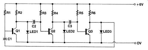
This circuit is easy to build and is a little unusual. It can be used to dress up many other projects and it only uses three transistors that you probably have lying around your workbench or in your junkbox. The circuit is a simple but not well known extension of the common "twin LED flasher." When power is first applied, two of the three 4.7uF capacitors will charge up before the third and turn the associated transistors on.
For example, if capacitor C1 and C2 charge up first, then transistors Q1 and 02 turn on, which causes Q3 to be turned off, so LED 3 lights up.
After a certain time, capacitor C3 charges up to eventually turn Q3 on. This causes capacitor Cl to be pulled low, and because it has no charge on it, the base of transistor Q1 is also pulled low. This turns this transistor off and LED 1 lights up. Meanwhile transistor Q2 is turned on because of the 10K ohm resistor pulling its base high.
The circuit then keeps looping around continually whenever the power is applied to the circuit.
Current consumption is around 10mA which should allow even small penlite cells to be used adequately.
CONSTRUCTION
As with all projects, construction is where the theory meets practice. If you follow the simple rules of construction, you should have no troubles with this circuit.
It is quite robust and will handle voltages of up to 40V or more depending upon the transistors you use.
Remember the higher the voltage you use, the higher in value the collector resistors R2, R4 and R6 must be, so that the current through the LED doesn't become too high and damage them.
As an example, this project can be used as a simple traffic light system for a model train layout. Using suit- ably large capacitors, you can increase the time the circuit takes to cycle through each LED. The simple rule is the higher the capacitor, the longer the delay time.
PARTS LIST FOR THE 3-LED SEQUENTIAL FLASHER
C1-C3-4.7uF, 25VW Electrolytic capacitors R1, R3, R5 -10K ohms, 0.25W Resistors R2, R4, R6-1 K ohms, 0.25W Resistors LED 1-3-5mm RED Type Q1-Q3-BC548 or any similar NPN (Hfe>100) type
---------------------
ELECTRONIC VHF TUNER
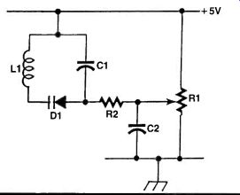
Most of us are familiar with the standard parallel inductor/capacitor combination found in the tuner section of radio circuits. For example, the crystal set has a coil or inductor at the front end with a variable tuning capacitor in parallel. Back in the old days, you could easily find these variable capacitors now, on the other hand, it's about as rare as a '55 Chevy. A common found bit of advice is to go and search in junk boxes at ham fests or the like. If, like me, you want a bit more solid advice then you'll like the suggestion below. As technology progresses the hobbyist unfortunately has to make do with whatever components the manufacturer decides to supply. So what can we use in place of the essentially defunct variable capacitor? The varicap diode is the answer! Not only is it avail- able now, it is also very simple to use & takes up less space. There is a trade off -- extra components are needed to drive it, but the design is still very simple. A varicap diode changes its capacitance as the voltage applied to it is varied. Hence when placed in parallel across an inductor, the resonant frequency will also change accordingly. The example shown here is configured for the VHF frequencies, around 88MHz to 108 MHZ, as this is where they work best (for hobbyist purposes). The tuning action is mechanically very smooth since a standard potentiometer acts as the tuner. Take a look at the circuit shown. The coil (L1) is the traditional VHF home wound item found in low power short range FM transmitter circuits. D1 is the varicap diode and has to be connected as shown to be reversed biased. The tuning voltage is supplied by R1. The rest of the components stabilize and buffer the voltages. There are many variations around this design, but this one is nice and simple to build and works very well. Next time you come across an FM transmitter circuit and can't find the variable capacitor, try this circuit instead.
PARTS LIST FOR THE ELECTRONIC VHF TUNER
L1-Hand wound VHF coil to suit circuit being used.
D1-Motorola MV209 varicap tuning diode
C1 -0.1 uF capacitor
C2 -0.1 uF capacitor
R1 -100K potentiometer
R2 -100K resistor
--------------------
HEADLIGHT MINDER
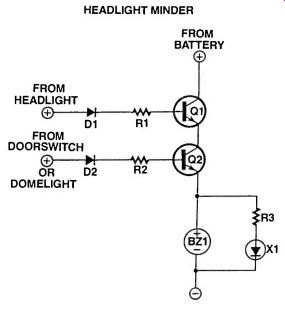
Not every vehicle has one of these circuits, but every one should. Picture this: You are out in the middle of nowhere, miles from the nearest service station. You stop, and leave the vehicle. Since it is twilight, your headlights are on, but there is no alarm. When you return to the vehicle, the battery is drained. When you install the Headlight Minder, the whole picture changes. As soon as you open the door of your vehicle, the buzzer squawks, and the LED flashes. Now, you remember to shut off the headlights before they can discharge the battery.
Construction is simple and the small board can hide anywhere behind the dash. You might put the circuit in a small plastic box to protect it from the elements or damage. The only component that need be visible is the LED and it is not a necessity to use an LED if you have the buzzer. Also, it is not necessary that the LED flash, but it enhances its ability to catch your eye Make sure you make your connection to the load or lightbulb side of the headlights switch and door switch. In the unlikely event that your vehicle does not have a dome light, a door -activated switch can be added.
Wire one side of the switch to the battery through a 1K-Ohm resistor of 1 watt, and the other side to the cathode of D2.
Test the device by turning on the headlights and opening the door of the vehicle. The buzzer should buzz and the LED should light. If so, the Headlight Minder is functioning properly.
This little device could be a lifesaver.
PARTS LIST FOR THE HEADLIGHT MINDER
R1, 2--10K Ohms 1/2 watt resistors
R3-1-K-Ohm
D1, 2-1 N4007 diodes
Q1, Q2-2N2222 transistors
X1-Flasher LED
BZ1 -12 volt buzzer or sonalert.
Misc.-Wire, solder, PC board, box, door switch if necessary.
+++++++++++++++++++++++
Also see:
INTRODUCTION TO STEPPER MOTORS
adapted from: Electronics Handbook XV (1994)