By John Iovine
Stepper motors are commonly used in robotics, automation and positioning control in commercial and industrial equipment. If you own a computer these motors are as close to you as your disk drive and printer. Stepper motors are used in these applications because they are easily controlled by digital circuits and most important, capable of precise positioning. This article will describe how to construct a simple stepper motor interface to examine the basic operating principals of stepper motors.
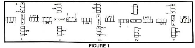
FIGURE 1
Stepper motors are different from normal electric motors. When you apply power to an ordinary motor the rotor turns smoothly. A stepper motor however, runs on a sequence of electric pulses to the windings (or phases) of the motor. Each pulse to the winding turns the rotor by a precise amount. These pulses to the motor are often called steps. Stepper motors are manufactured with different amounts of rotation per step (or pulse), depending upon the application it is designed and built for. The specifications of the stepper motor will state the degree of rotation per step.
The range of rotation per step can vary from a fraction of a degree (i.e. .72 degree) to many degrees (i.e. 22.5 degrees).
Basic Operations
Figure 1 is of a stepper motor stepping through one rotation. Stepper motors are constructed of strong permanent magnets and electromagnets. The permanent magnets are located on the rotating shaft; called the rotor. The electromagnets or windings are located on the stationary portion of the motor called the stator. The stator, or stationary portion of the motor surrounds the rotor.
In figure 1 position I, we start with the rotor facing the upper electromagnet that is on. Moving in a CW (clockwise) rotation the upper electromagnet is switched off, as the electromagnet on the right is switched on. This moves the rotor 90 degrees in a CW rotation, shown in position II. Continuing in the same manner, the rotor is stepped through a full rotation until we end up in the same position as we started, shown in position V.
Resolution
The degree of rotation per pulse determines the resolution of the stepper motor. In the illustrated example, the rotor turned 90 degrees per pulse, not very practical. A real world stepper motor, for instance, one that steps 1 degree per pulse would require 360 pulses to achieve one revolution. Another motor with less resolution (greater degree per step), that steps say 3.75 degrees per pulse would only require 96 pulses for one full rotation.
Without getting into gearing or gear ratios. Let's assume that the stepper motor is used for positioning in a linear motion table, and further that each revolution of the motor is equal to one inch of linear travel on the table. It becomes apparent that each step of the motor defines a precise increment of movement.
In making a comparison between the two stepper motors, the ability to locate and position more precisely on the table would be with the stepper motor with the higher resolution (one that requires the most steps per revolution). For the motor that steps 3.75 degrees per step, the increment of movement is approximately .01 inch per step. If this resolution is sufficient for your table it's fine to use this stepper motor. If however you required greater resolution the 1 degree per step motor would give approximately .0027 inch per step. So you see the increment of movement is in proportion to the degrees per step.

-------FIGURE 2
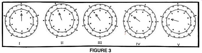
-------FIGURE 3
Half Step
It is possible to double the resolution of some stepper motors by half stepping. In figure 2, this is illustrated. In position I, the motor starts with the upper electromagnet switched on, as before. In position II the electromagnet to the right is switched on while keeping power to the upper coil on. Since both coils are on, the rotor is equally attracted to both electromagnets and positions itself in between both positions (a half step). In position III the upper electromagnet is switched off and the rotor completes one step. Although we are only showing one half step, the motor can be half stepped through the entire rotation.
Other Types of Stepper Motors
You may run a 4-wire stepper motor. These stepper motors have two coils, with a pair of leads to each coil.
Although the circuitry of this stepper motor is simpler than the one we are using, it requires a more complex driving circuit. The circuit must be able to reverse the current flow in the coils after it steps.
Real World
As stated, the stepper motors diagramed for illustration wouldn't be of much use in the real world, rotating 90 degrees per step. Real world stepper motors employ a series of mini-poles on the stator and rotor which improves the resolution of the stepper motor. Although figure 3 may appear more complex than the previous figures it is not really so. Its operation is identical, and to prove the point we'll step through the illustration.
In figure 3 the rotor is turning in a counter clockwise (CCW) rotation. In position I the north pole of the permanent magnet on the rotor is aligned with the south pole of the electromagnet on the stator. Notice that there are multiple positions that are all lined up. In position II the electromagnet is switched off and the coil to its immediate left is switched on. This causes the rotor to rotate CCW by a precise amount. It continues in this same manner for all the steps. Examine the pole relationship between IV and V. The rotor is still moving CCW, and in position V the stator poles are in the same orientation as position I. This is where the sequence of electric pulse would begin the repeat themselves and keep the rotor turning CCW. Figure 4 illustrates the half step with the multi-pole position. It is identical to the half step described before.
Test Circuit
With this manual circuit, you can check and verify your wiring of the stepper motor. In addition it's an excellent tool to use if you are checking out a different stepper motor from the one used in this article.
Look at figure 5. The circuit is the epitome of simplicity. Switches S1 thru S4 are normally open subminiature push button switches, see parts list. The four switches allow you to drive the stepper motor manually.
By changing the sequence of the steps we can do full step and half step increments in either direction (CW or CCW). The diodes D1 thru D4 are used to prevent sparking and protect the balance of the circuit. These diodes become more important when the motor is interfaced to a computer. The batteries used in the circuit are two small 12 volt batteries in series to generate the 24 volts required. The stepper motor we are playing with is a 24 volt model. The rectangular box at the top of the diagram with six head screws are six PC Board Terminals interlocked together, see parts list.
This simplifies connecting the wiring from the motor to the circuit.

-------FIGURE 4
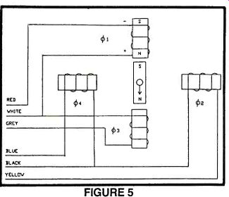
-----FIGURE 5
Stepper Motor
Figure 6 is an electric equivalent circuit of the stepper motor we are using. The stepper motor has 6 wires coming out of the casing. We can see from figure 6 that 3 leads go to each half of the coil windings. And that the coil windings are connected in pairs. If you just selected this stepper motor and didn't know anything about it, the simplest way to analyze it would be to check the electrical resistance between the leads. By making a table of the resistances measured between the leads you'll quickly discover which wires are connected to which coils.
On the motor we are using there is a 60 ohm resistance between the center tap wire and each end lead, and 120 ohms between the two end leads. A wire from each of the separate coils will show an infinitely high resistance (no connection) between them. Armed with this information you can just about tackle any 6 wire stepper motor you come across. The stepper motor we are using rotates 3.75 degrees per step.
Test Circuit Demo
When you have finished wiring the test circuit and connecting the stepper motor, use the following two tables to step or half step the motor.
FULL STEP HALF STEP
When you reach the end of the table the sequence repeats starting back at the top of the table.
If you want to reverse the direction of travel just reverse the sequence of the table, starting from the bottom and working to the top.
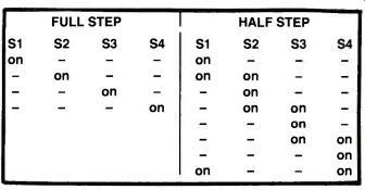
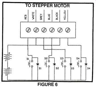
FIGURE 6
Trouble Shooting If you use the stepper motor listed in the parts list I don't think you'll run across any problems. If you should, the first thing to check is the diodes, make sure you have them in properly, facing in the direction shown in the schematic.
If the stepper motor moves slightly and quivers back and forth, chances are the batteries are too weak to power tie motor, replace them with fresh batteries. The batteries do wear out pretty quick. This problem can be solved by modifying your existing circuit board to use line voltage with a step-down transformer, rectifier and capacitor.
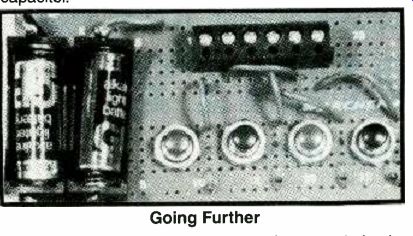
Going Further
There are a number of dedicated integrated circuits available for powering and controlling stepper motors.
SUPPLIER INDEX
Stepper Motor 6 wire $10.00 postage $ 2.50
Available from: Images Company P.O. Box 140742 Staten Island, NY 10314-0024
PARTS LIST
RADIO SHACK
D1-D4 1N914 Diode RS#276-1620 PC Board Terminals Stackable RS#276-1388 S1-S4 Momentary push switch (4/pak) RS#275-1547c Battery holder RS#270-405 Battery RS#23-144 PC Board RS#276-170 RS = Radio Shack (local)
+++++++++++++++++++++++
Also see:
adapted from: Electronics Handbook XV (1994)