
By Darren Yates
Ounce for ounce and for the relative low cost, diodes are probably the most useful component ever produced and they can certainly do more than just make your power supply function.
If you visit your local electronics supply store and invest the pocket change necessary to purchase a 1N4004 or whatever diode, you're buying a lot more than just a rectifier diode.
Diodes have been used for years as power rectifiers for power supply but they can also be made to do other jobs including voltage multiplying, digital logic functions, amplitude modulation and detection, audio signal expansion and compression and a few other things we'll observe along the way.
Ok, so where do we start? Perhaps it would be a good idea to take a close look at this tiny two lead device and see what makes it tick.
A diode has two leads, just like a resistor and often looks like that shown in figure 1. The biggest difference between the diode and the resistor, however, is that a diode will only allow current to flow in one direction.
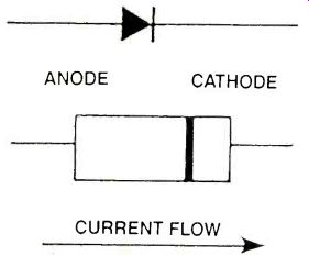
FIGURE 1: PHYSICAL APPEARANCE OF A DIODE
Unlike a resistor, there has to be some way to identify which end of a diode is which, otherwise we'll end up with all sorts of problems. As you can see in figure 1, near one end of the diode there is a single colored bar that runs around it. The end furthest from this is called the ANODE and the end closest is called the CATHODE.
Current always flows only from the anode to the cathode. An easy way to remember this is that "A" (for anode) comes before "C" (for cathode) in the alphabet and current always hits the anode before the cathode as it flows through the diode.
Above the physical diagram in figure 1 is the graphical symbol for a diode, which is a triangle pointing in one direction, with a bar at the end of it. This symbolizes that the current flow is in the direction of the arrow but that it doesn't flow back the other way.
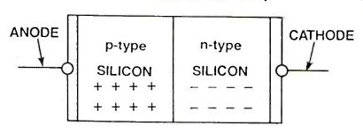
FIGURE 2: PHYSICAL STRUCTURE OF A SILICON DIODE
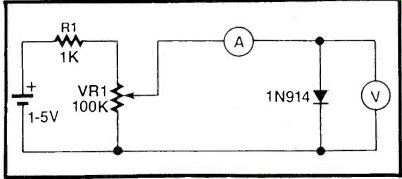
FIGURE 3: BASIC CIRCUIT TO TEST HOW A DIODE WORKS
A diode, however, is more than just a one-way piece of wire. It is the simplest semiconductor junction that can be produced, and is called a "pn junction". If you take a look at figure 2, you'll see the reason why.
Back in the early days of semiconductors, diodes and transistors used to be made from a poisonous substance called Germanium, but now they are all made out of the much safer, silicon.
Without going into unnecessary detail, the n-type silicon is a thin wafer of silicon material which has an excess of electrons and the p-type silicon has an excess of what we can call "holes". These are really gaps in microscopic atoms where electrons would normally be.
These holes are produced by a method called "doping" (seriously!), which is the controlled addition of impurities into the silicon. The most important thing here, practically-speaking is that the amount of current flow between the two silicon regions, from the positive region to the negative region, is determined by the voltage across the two regions.
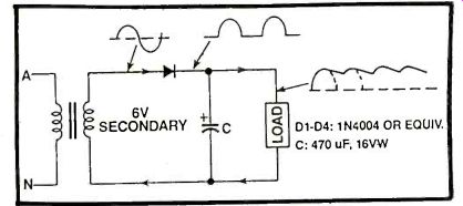
FIGURE 4: HALF WAVE RECTIFIER
This may sound a bit confusing but we'll explain it by giving an example. If you look at the circuit in figure 3, we've made a little test jug so you can have a go yourself and see what happens.
If you can get hold of two multimeters (they don't need to be digital ones and it would probably be better if they weren't), select one of them on the 0-2 mA range (or similar) and the other on the 0-1 V range.
Connect the mA multimeter in the circuit as shown and connect the volt multimeter across the diode. Now if you connect up the 1.5V battery, we're ready to go.
Start with the variable resistor so that there is maximum current flowing through the diode. You should find that there is about 0.8mA of current flowing through the multimeter and that there is about 0.6 or 0.7V or so across the diode. Now if you rotate the variable resistor, the current should start to drop but when the voltage across the diode drops below 0.5V or so, you should see the current start to drop off dramatically.
The current will drop anyway when you start to turn the variable resistor around, but it's when the diode voltage begins to drop that is most important.
The reason for this is that the diode must have a voltage across it before it will conduct a current, but as it approaches about 0.6V, the current flowing through it will increase enormously for very little change in the voltage across it. This is because the voltage acts like a "step" to lift up the energy level of the p-type region so that current flows.
OK. So we've established that a diode only conducts in one direction, namely, from the anode to the cathode and that there is a "voltage drop" of about 600mV (or 0.6V) across the diode when it is conducting.
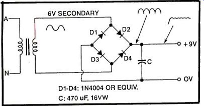
FIGURE 5: FULL WAVE RECTIFIER CIRCUITS
That's enough of the boring stuff! Let's see how we can make the diode do different things!
HALF-WAVE RECTIFIER
Figure 4 shows the most common and basic circuit for a diode. This is a simple half-wave rectifier, a "bread and butter" circuit for the diode.
The idea of the circuit is to turn the AC power coming from your wall outlet into DC that your Walkman, video recorder, CD and thousands of other items can use.
AC power is a sinewave with a frequency of 60Hz and has a voltage of 115V (in Australia, the frequency is 50Hz and the voltage is 240V). Your Walkman only requires about 3VDC so we must change the type of voltage as well as drop it down a long way.
To drop the voltage down, we use a device called a transformer, which as its name suggests, transforms the voltage to another value. Transformers can be made to make the voltage higher (called a "step-up transformer") or lower (called a "step-down transformer"). What we need for our job is a step-down transformer. You won't be able to see the difference between the two from the outside.
Underneath the layers of tape you can see, are two fairly large coils, which are just windings of wire. The amount of voltage you get at the output depends on the ratio of turns between the two coils.
For example, for our simple circuit, we'll have 115 Vrms (we'll explain the "rms" a little later) on the input and we'll need 3VDC at the output. Jumping ahead a little, using our single diode power supply circuit, the output in DC voltage is about half the RMS voltage.
Since we need 3VDC, that means we need about 6Vrms at the output end of the transformer. Remember that a transformer just changes the voltage level: it doesn't turn AC power into DC! So, for our transformer, we need 115V going in and 6V going out. Now remember how we said that the voltage depended upon the number of turns in each winding, well, the ratio of the number of turns of the "primary winding" (that's where the 115V goes) and the "secondary winding" (that's where the 6V comes out of) needs to be 115/6 which is nearly 20:1.
A "turn" is simply a complete circle of wire, usually enameled, around the transformer.
That means any transformer with either 40 turns on the primary winding and 2 turns on the secondary or any multiple (up to a point) of these will be suitable.
OK, we've got off the track a little but it is important to know howeverything works otherwise you'll miss out on the important bits.
Now that we have our 6V coming out of the transformer, we still have the problem of turning it into DC. Since it is still AC at the moment, the voltage keeps changing polarity. If we look back to figure 4, let's consider what's happening at both sides of the diode. Half the time, the anode voltage will be positive and the cathode end will be negative, but the other half of the time, it swaps around! If you connected this changing voltage to your Walkman, it would give up and die in a second! Now you can probably see the reason for the diode. Remember we said that a diode will only conduct current one-way? We also said that this only happens when the anode end is positive with respect to the cathode end.
What simply happens in our circuit is that for half the time the anode is positive, the diode allows a current to pass through, and when it is negative, it stops the flow.
If you were to look at the waveform of the power coming out of the diode, it would look that drawn in figure 4.
Even though it does look a little sick, the current flow is only in one direction, i.e. we have DC. If you measure it with a voltmeter, it would be around 3VDC even though we have 6 Vrms coming out of the transformer.
"RMS" stands for Root-Mean-Squared which is a way of describing the absolute voltage level of an AC power line. Since our diode chops off the negative half of the sinewave, we only end up with half the voltage, hence the 3V. The DC we end up with coming out of the diode is still pretty awful, so we add a filter capacitor which smoothes the waveform a bit more. Now we have a quite acceptable power supply! The filter capacitor also boosts the voltage up to about 6VDC. This is because the capacitor acts like a storage cell, provided the load current is not too large, to provide a more constant level of voltage. As the load current increases, the voltage will drop down. This is because the load current is being taken from the capacitor continuously, but the capacitor itself, is only being topped up for half the time i.e. when there is a positive current flow.
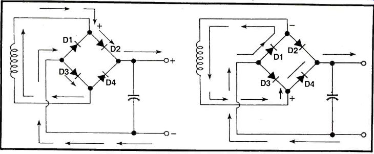
FIGURE 6: CURRENT FLOW DURING BOTH HALVES OF THE SINEWAVE
FULL-WAVE RECTIFIER
Although the half-wave rectifier is simple, it wastes half the power we could use if we had the right circuit, and as we've just shown it cannot consistently supply a constant voltage under heavy load currents.
Figure 5 shows a full-wave rectifier. It's so named because it turns both halves of the wave so that the current continually flows in the one direction.
The four diodes are connected so that they form a diamond shape with each diode pointing from left to right. This configuration is called a "diode bridge". Every point on the bridge has two diodes connected to it. Notice that there are two points on the bridge where a diode is pointing to it and another diode pointing away from it. The secondary winding of the transformer is connected to the points. The other two points have both diodes pointing away from it or pointing to it.
Our DC voltage is taken from these points: the point where both diodes are pointing away from it is zero volts or ground and the other end is the positive end.
The operation of this type of rectifier is not obvious so we'll explain it in detail.
Remember how we said before that the voltage across the secondary winding changes polarity, one minute one is positive and then next, the other end is? This voltage is applied to the bridge, which works like this: Looking at figure 6, if we assume to start with, that the end of the transformer connected to diodes D1 and D2 is positive and the other side of the transformer is negative, then current flows through D2, out through the load you have connected to the circuit, then back through the ground line, through diode D3 and to the transformer.
At this stage, no current flows through diodes D1 and D4 because they are reversed biased i.e. the cathode ends are at a higher voltage than the anode ends of both diodes.
Now, when the voltage across the transformer changes polarity, the point connected to diodes D3 and D4 is now more positive than the point connected to diodes D1 and D2.
This time, current flows through D4 to the load, then back through the ground line and then to the transformer via diode Dl. Also, diodes D2 and D3 are now reversed biased so no current flows through them.
The filter capacitor at the output shown in figure 5 does the same job as that shown in the half-wave rectifier circuit, but in this case the capacitor is being topped up by every half cycle instead of every second one. This means that it can supply a much larger current to the load while still maintaining its output voltage.
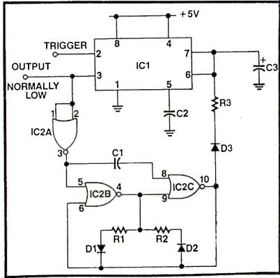
FIGURE 7: LONG DELAY TIMER CIRCUIT
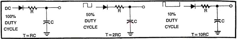
FIGURE 8: THE CONSTANT OF A CHARGE-PUMP CAN BE VARIED BY USING A PULSE
TO CHARGE THE CAPACITOR
LONG DELAY TIMER
Let's depart from power supply circuits for a while and look at a different use for the diode.
Most of you would probably know how a 555 timer IC works, in fact, you probably have one or two lying around on your bench or in your "junkbox;'. They are a vey useful IC, particularly as a "one shot" or monostable. This is where the IC is triggered by a negative-going pulse, which produces a high output for a particular length of time, determined by an external resistor and capacitor.
The problem occurs, however when trying to create delays of 10 seconds or more. The equation for the time delay is as follows: T = 1.1 x R x C, where R is in ohms and C in farads.
If we wanted to generate a 20 second delay, we would need a 1M resistor and 22uF electrolytic capacitor (or thereabouts). That's OK in theory, but in practice, electrolytic capacitors are renown for their high leakage current. This results in the time delay being inaccurate, depending on how much leakage current there is.
The circuit in figure 7 fixes this problem and also enables the generation of time delays up to about 40 minutes with a high degree of accuracy.
Furthermore, it uses diodes to do two totally different things, both of which are vital for the circuit's operation.
The operation of the 555 is as usual except that when the trigger is applied to IC1, the capacitor is no longer charged up from the power supply as in the usual way, but instead, from a pulsed output coming from IC2c.
Before we go any further, we should explain how this is possible.
Capacitor C3, diode D3 and resistor R3 form what is known as a "charge pump". Figure 8 shows how this works.
In figure 8a, the capacitor is charged up through the resistor and the diode by a DC voltage. In this circuit the diode doesn't do anything.
If we say this circuit has a time constant of R x C, we mean that it takes R x C seconds to reach a certain point. It isn't important for the moment what that certain voltage is, since the capacitor charges up at a logarithmic rate. What is important is this rate or speed at which the capacitor charges.
If we now take a look at figure 8b, instead of feeding the charge pump with straight DC, we use a square wave. This is where the diode comes into action. A squarewave as its name suggests-is high for half the time and low for the other half.
If we place a diode in series with the RC circuit, we stop the capacitor from discharging through the resistor when the input goes low again. Therefore, we get a series of positive pulses which charge up the capacitor, but because the pulses only occur for half the time, we get a DC voltage for only half the time.
This means that it takes twice as long for this circuit to charge the capacitor up to the same level it would if charged up with the circuit in figure 8a.
If we look at figure 8c, the input signal is a 10% duty cycle pulse. To explain this, "10% duty cycle" means that the positive pulse occurs for 10% of the time. Notice this is regardless of the frequency. If we consider DC as a 100% duty cycle then it should be clear that if we feed the charge pump in figure 8c with a 10% duty cycle that it must take 10 times longer to charge up the capacitor to the same level as that in figure 8a.
The threshold input of the 555 is when the capacitor voltage is 2/3rds of the supply voltage. Thus by using pulses to charge up the capacitor rather than DC, we can vary the time it takes to reach this point.
OK. Now we have to find some way of producing the pulses when we want them.
When a negative trigger is applied to pin 2 of the 555 timer, the output at pin 3 goes high. We can use this to turn on an oscillator which can then be used to fill up our charge pump.
If you look back to the circuit in figure 7, IC2 is a CMOS 4001 quad 2-input NOR gate IC package. The first gate, IC2a, is connected as an inverter to the output of the 555 timer. The output of IC2a is then used to turn off and on, the pulse generator made up of IC2b and IC2c.
Before we go any further, we should explain a couple of things. The reason we used a 4001 is because when the pulse generator is turned off, we want the output to be held low. If it is held high, which is what would happen if we used a 4011 NAND pulse generator, the charge pump would fill up too fast as normal and defeat the purpose of the circuit.
To make a NOR pulse generator work, we must make the control input low and then make it high to stop it at the appropriate time.
Resistor R1 and R2, and diodes D1 and D2 determine the pulse width and hence the time delay.
The diagram in figure 9 will help explain how this works. Looking at the first half of the diagram, let's assume that the output of IC2c is high, and it's filling up the charge pump (D3, R3 and C3). This means that the output of IC2b is low, because it, too acts as an inverter, so capacitor C1 is charged up from the high output of IC2c, through diode D2 and resistor R2.
Looking now at the second half of the diagram, once the voltage across this capacitor reaches the threshold level of the input to IC2c, the output will drop low. Capacitor C1 will now discharge through resistor R1 and diode D1 to the low output.
The diodes make sure that the current flow is split into two paths depending on which way it's flowing. If the current is flowing from the output of IC2c, it passes through diode D2 and resistor R2, and if it's flowing back to the output, it passes through resistor R1 and diode D1.
If both resistors are made the same value, then the output of IC2c will be a square wave, but if we make one resistor bigger or smaller than the other, then the pulse width will depend on the ratio of the two resistors.
If we make R1 ten times as big as R2 then we'll get a 10% duty cycle (very narrow) pulse. If we make R2 ten times as big as R1 then we'll get a 90% duty cycle (very wide) pulse.
As an example, if we make R1 equal to 1 M-ohm and R2 equal to 1 Kohm, then the circuit will give us an "on time" of approximately 37 minutes. You could use this circuit to turn your Walkman on, and then it will automatically turn itself off after that time has expired.
Or, if you're very careful, you could use this as a power appliance time, say for an iron, so that it turns itself off after the desired time interval. Anyway, the choices are only left up to your imagination! Next time, we'll have a look at audio applications of diodes including signal compression and amplitude modulation. See you then!
PARTS LIST
C1--0.01 uF Mylar Capacitor
C2--0.1 uF Mylar Capacitor
C3--2.2 uF, 25 VW Tantalum Capacitor
D1-D3--1N4001 Diodes or similar
IC1 LMC 555 CMOS Timer
IC2--4001 CMOS Quad 2-input NOR Gate
R1, R2--See text
R3--1 M ohm, 0.25W Resistor
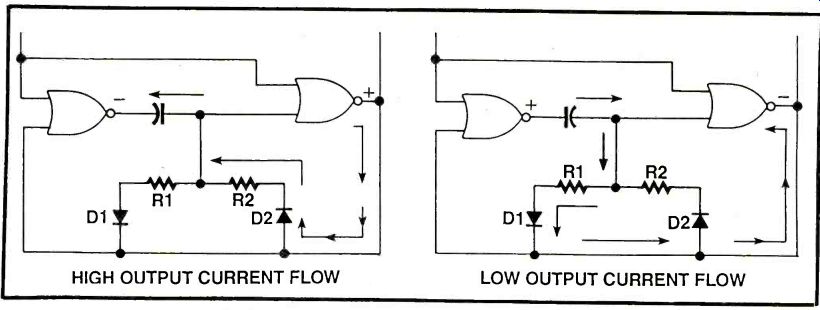
FIGURE 9: OPERATION OF A PULSE GENERATOR
Also see: Power Supply Basics
adapted from: Electronics Handbook Vol. X