By Homer L. Davidson
The integrated circuit (IC) is a component made with various parts connected together in one chip. The chip is a semiconductor material constructed from silicon. IC's are made up of capacitors, resistors, transistors, and connecting wires in several circuits inside one component. Today, IC components are found in radios, receivers, amplifiers, telephones, CD and cassette players, computers, VCR's, TV sets and other electronic devices.
The first linear IC's were used in the audio amplifier section of the cassette player and TV chassis.
The first IC's were mounted in a round case, like the transistor, and now are found in flat packages, mounted vertically, horizontal and flat against the PC board.
Later, digital, Op-Amp, COS, MOS, CMOS, PMOS, DTL and TTL integrated circuits and micro-compressors were introduced and are located in many electronic circuits.
A micro-compressor may have from 22 to 80 terminals and are found in VCR's, camcorders, CD players and the TV chassis. The microcomputer component in a single integrated circuit is designed around a micro compressor. You may find a separate micro-compressor and microcomputer component inside the tuning section of the TV chassis. (Fig. 1).
IC Symbols
The IC symbol found in the schematic may appear as a rectangular box or a three cornered drawing. The IC may have numbers around the component indicating the terminal connections. Most schematics do not show the internal components or stages, inside the IC, connected together (Fig. 2). The integrated-internal component block diagram can be found in universal semiconductor replacement manuals.
Usually, the operational amplifier (OP-Amp) is identified with a triangular shaped box with inputs 1 and 2, and output terminal. The Op-amp IC can be found in a round or flat package. You may find two or more OP Amps inside one component within the VCR, camcorder and TV set (Fig. 3). Notice the OP-Amp has negative and positive input terminals. The OP-Amp is used in amplifiers, linear control applications, and in motor control circuits.
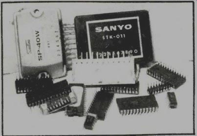
Fig. 1. IC parts appear in many different sizes and shapes, with flat or
edge mounting.
Identification
IC components can be mounted through holes in the PCB or surface mounted. Some are mounted or plugged into a socket (Fig. 4). Surface mounted IC's (SMD) mount directly on the PC wiring, while other IC components are on the top side of the chassis. IC parts in VCR's and the TV set may have SMD parts mounted between the IC pins of a regular IC component, that is mounted on the top side with SMD parts on the PC wiring.
All terminals on the IC component, in the circuit, are identified with different numbers on the IC. To determine the input and output terminals, operating supply voltage (Vcc), bias and ground terminals, the correct numbers maybe found on the top side of the IC. The supply voltage pin is always the highest measurable voltage. Locate terminal #1 of the IC and count down each side ford the correct pin terminal. Sometimes you may find no terminal pin numbers stamped on the IC terminals, while in other circuits the pin terminal may be numbered at the corners of the PCB.
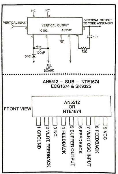
Fig. 2. A schematic of a vertical output IC402 (AN5512) with corresponding
numbered terminal pins.
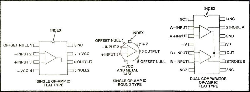
Fig. 3. The OP-Amp semiconductor may be found inside a flat or round mounting
with one or more circuits.
Locate terminal one with a white or black line at one end of IC, a white dot or circle, and an indent "U" shape at one end of IC (Fig. 5). You may find only one of these identifications on the body of IC or two or more identifying markings. Terminal #1 is always to the left side of the indent, white or dark line. A white or clear circle indicates terminal one is on top of the IC body. Notice that in this 16 pin IC, terminal 9 is across from 8 at the opposite ends.
Flat vertical and horizontal mounting IC's can be identified with a white dot, clear circle, "U" at one end, and a slanted cut off corner at one end of IC (Fig. 6). You will find this type of IC mounting in motor and control circuits of CD, camcorder and VCRs. The metal flange or IC's with a metal back are found in power output amplifiers and vertical output circuits within the TV chassis. Lower signal or power IC's are mounted like transistors, without a metal heat sink. All high powered IC's are mounted on separate heat sinks. Most IC's can be mounted directly into holes of the PC board and soldered to the PC wiring.
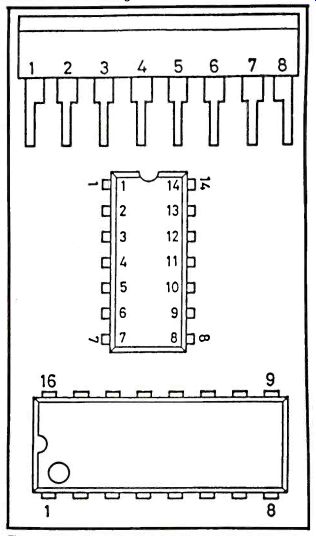
Fig. 4. Notice where terminal one starts at the indent, circle and slanted
edge mounted IC.
Simple Project IC Components
Today, you will find more IC components used in electronic experiments and construction projects than transistors (Fig. 7). A single shortwave receiver may have a high gain AF IC to drive a pair of earphones.
The LM386 IC can be found in many audio circuits of electronic projects. Here, a low audio signal can be amplified to drive earphones or a small speaker.
The LM386 IC can be identified with a white line or circle. Notice the pin connections shown on the body of the IC, while looking down on the IC component (top view). The audio signal is coupled to input pin 3, amplified and capacity coupled through a 220uF electrolytic capacitor to the PM speaker. Pin 6 is the voltage supply pin connected to a 9 volt battery source (Fig. 8). The 220uF capacitor connected to pin 6 and ground prevents oscillations occurring in the audio circuit.
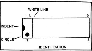
Fig. 5. Identify pin number 1 with indent, circle or white and dark line,
on top, at one end of the IC.
Simple Tests
The IC component can be checked with an input-output signal and voltage tests. Check the input signal at the input terminal and then the output terminal of an audio IC with another external audio amp or scope. If the audio signal is found at the input and not at the output terminal, suspect a defective IC, outside components, or improper supply voltage. Then take voltage and resistance measurements on the IC terminals, to locate a defective IC or connecting part.
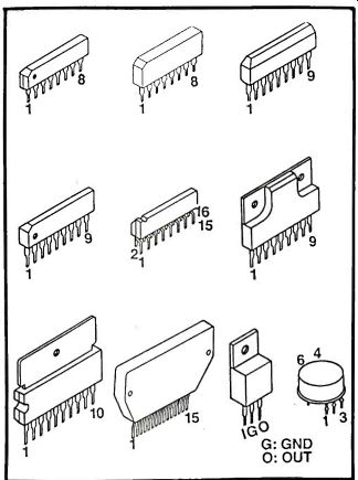
Fig. 6. Notice the slanted edge mounted IC for terminal #1.
Large power IC devices mount flat against a metal heat sink.
Besides voltage and resistance tests on the IC terminals, a defective IC can be located with the oscilloscope in the VCR, CD, and TV chassis. Waveforms taken on the input and output terminals can identify a defective IC or circuit. Critical waveforms taken on transistor and IC components within the vertical and horizontal circuits of the TV chassis can determine what stage is defective. The defective IC can become leaky, open internal circuits, or have shorted terminals. Remember, the integrated circuit cannot be tested like a regular transistor.
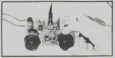
Fig. 7. This small audio amplifier project is constructed around an 8
pin LM386 IC.
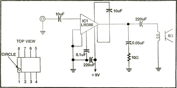
Fig. 8. The 8 pin (LM386) amplifies the weak detected shortwave signal
to drive a pair of low impedance earphones.
Voltage and resistance tests
Critical voltage and resistance measurements on each terminal pin to common ground may determine if the IC is defective. Start with the voltage pin and compare voltage measurements with those on the schematic (Fig. 9). If a diagram is not available, the supply voltage should equal the battery or low voltage supply source. Then check each voltage on the remainder of the pin terminals.
Often, a low DC supply voltage indicates a leaky IC or improper battery or DC voltage source. Remove the supply pin from the PCB circuit, with a soldering iron and solder wick. Make sure all solder is removed from pin terminal and pc wiring. Now take a voltage measurement at the pc wiring, where the pin terminal was connected. The IC is leaky if the voltage increases at the voltage supply source. A low voltage measurement indicates improper low voltage source. Check for weak batteries or low voltage power supply.
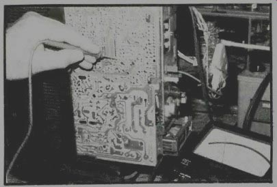
Fig. 9. Take critical voltage and resistance measurements on the suspected
IC to determine if the IC is defective.
When taking a low resistance measurement that is lower than shown on the schematic, suspect a leaky IC component or part tied to that pin terminal. Remember, these voltages may be less than 1 volt and should be taken with a DMM. The supply voltage source is always the highest voltage found at any IC pin terminal. In battery operated projects the supply voltage IC source equals the total voltage of all batteries (Fig. 10). With a low voltage measurement on a certain pin number, take a critical resistance measurement to chassis ground. Make sure a low ohm bias resistor or ground IC terminal is found on the schematic. Check the resistance measurements of each pin terminal to ground, to determine if the IC is defective or a leaky component is tied to it. Bypass capacitors have a tendency to become leaky between pin terminals and common ground. Likewise, resistors can become open or increase in value. Remove one terminal of the component and take another resistance measurement.
Make sure all components tied to the suspected IC are normal before attempting to remove the integrated circuit (IC). If not, the IC may be good and you have gone to a lot of work removing and replacing the suspected IC. When voltage and resistance measurements are normal with normal input and no output signal, install a new IC replacement.
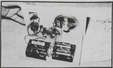
Fig. 10. In battery operated projects, the voltage supply pin of the suspected
IC should equal the total battery voltage in that circuit.
Intermittent IC
In the stereo audio output circuit, one channel may be normal and the other distorted and weak in a dual IC audio component. Usually, when both channels are weak or distorted, suspect a common IC component. If one channel is intermittent and the other normal, you may find a defective IC or intermittent component tied to the intermittent audio channel.
Check the audio output IC for an extremely warm body by holding a few fingers nearby. If not, momentarily touch the body of the IC. A red hot IC will show signs of overheating, with white and brown stains on the body of IC. Be careful not to burn your fingers with a red hot IC. A normal IC may operate warm, but not be too hot to touch.
Sometimes the intermittent IC can be located by applying several coats of coolant on the IC. If the intermittent condition does not exist again, give it another spray treatment with coolant. Replace the intermittent IC when cold spray makes the sound go up or down (Fig. 11).
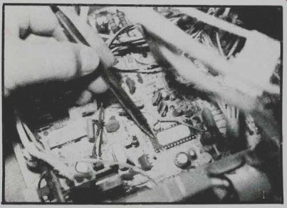
Fig. 11. The intermittent IC can be located by spraying several coats of
coolant on the body of the IC or microprocessor.
Removing the Defective IC
After making all tests and determining if the IC is defective, remove it from the pc wiring. The best and cheapest method is with a soldering iron and solder wick. The copper or tinned mesh material picks up the melted solder from the pins and the board wiring. Place the solder wick braid along side the row of bottom pin terminals. Place the iron tip on top of braided mesh and slowly go down one side of IC pins as the solder melts.
Now go down each side of pin terminals to unsolder each pin. Go over each pin to be sure the pin is loose from the copper PC wiring. Be very careful not to apply too much heat to pull or lift the foil from the PC board.
Also, be very careful not to damage other components with the hot iron. Take a pocket knife or screwdriver and flick each pin to make sure it is loose and no solder is left around it.
Before lifting the IC out of the PCB holes, mark terminal #1 on the PC board with a felt pen or a dab of white correction fluid. Some chassis may have an indent or terminal one (1) marked on the PC board, while others may have each pin at both ends marked on chassis. Do not use the removed IC again.
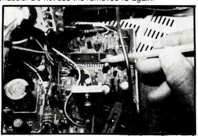
Fig. 12. Check the unknown IC part number at top of IC and refer to a universal
semiconductor manual to determine what stage It operates In, voltage
and current ratings, and what circuit each pin number ties to.
IC Replacement
In electronic projects, the IC part number can be found within the part lists. Likewise, in all consumer electronic products, the service manual provides a parts list. If you do not have a schematic, and no part list is found, check the letters and numbers on the top side of IC (Fig. 12). This component number can be looked up in universal replacement semiconductor manuals for the correct replacement. Look up the part number in an NTE Electronic (NTE), Sylvania Corp (ECG), and Thomson Consumer Electronics (RCA SK Series) replacement manuals.
Universal replacements can be replaced in most commercial electronic products when the original part is not available. Always, try to obtain the original part from the place where the product was purchased, manufacturers parts depot, or the manufacturer. Try to obtain the part from a local electronics dealer or wholesale distributor. Sometimes exact foreign or Japanese IC components can be purchased from mail order firms. Check with your local Radio Shack store.
TESTING AND REPLACING INTEGRATED CIRCUITS
Soldering Up Check for terminal #1. Mount the IC replacement from the top side of the chassis. If the IC is mounted backwards, you can destroy the new IC and other board components. Bend over two terminals at each end of the IC, so that when the chassis is turned over for soldering, it will not fall out. Make sure each pin is through the corresponding holes. Likewise, when mounting the IC into a socket, make sure all pins are in the socket.
Solder all terminals with a low wattage (30 watts) soldering iron. The battery soldering iron is ideal for transistor or IC circuits. Make good soldered connections, but do not leave the iron on the pin terminals too long.
Check each pin for a good connection with a magnifying glass. Inspect for excessive solder between two or more pin terminals. Remove excess solder with solder wick and iron. Check each pin terminal to the same PC wiring with the low ohm range of DMM. Sometimes the foil will lift up or pull off when the IC is removed, breaking the foil connection. Clean off wax and rosin flux with a general purpose electronic cleaner/degreaser spray.
ABBREVIATIONS
CDS-Complementary symmetry device
MOS-Metal-oxide semiconductor or Metal oxide silicon
CMOS-Complementary Metal-oxide semiconductor
PMOS-P-channel Metal-oxide semiconductor
DTL--Diode-transistor logic
TTL--Transistor-transistor logic
The abbreviations of various transistor and IC components.
Also see: IC Testbench
adapted from: Electronics Handbook Vol. X