by Dr. Ir. A.H. Boerdijk
A portion of the current-voltage characteristic of certain devices, such as the thyristor, the tunnel diode and the magnetron, has a negative slope, that is, the current decreases with increasing applied voltage or the voltage drops when the current increases. This behavior is, of course, opposite to that of an ohmic resistance. Whereas an ohmic (positive) resistance consumes power, a negative resistance appears to supply power. Negative resistance may be simulated electronically as described in this article.
From a pure arithmetic point of view, negative resistance remains resistance with the only difference that it is preceded by a minus sign. Figure 1 shows a conventional ohmic resistance and a negative resistance with an identical voltage applied across them. The difference in behavior of the two is clear: the currents through them flow in opposite directions.
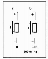
Fig. 1.

Fig. 2.
When a positive and a negative resistance are connected in series or parallel as shown in Fig. 2, the results are very interesting. The series combination (Fig. 2a) yields a short circuit: Rs= R +(-R)= 0. The parallel network (Fig. 2b) yields R = -R2 I [R + (-R)] = -R 2/0 = -00, P that is, a perfect insulator.
To confuse you further, in Fig. 3 a 10-V potential is connected across a series combination of a positive resistance of 1001 kS2 and a negative resistance of 1000 k-Ohm.
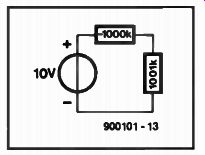
Fig. 3.
The total resistance in the loop, ignoring the internal resistance of the voltage source, is 1 ka The current flowing in the loop is therefore 10 mA, and this causes a drop of 10.01 kV (!) across the 1001 k-ohm resistance.
This does not indicate a new way of generating very high voltages, of course, as a quick consideration of the power distribution shows.
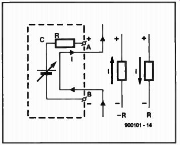
Fig. 4.
In Fig. la, the positive resistance dissipates a power P = P R or P =U2I R, whereas in Fig. lb the negative resistance delivers power to the voltage source. This means that negative resistance is not just a passive component and also that it can not exist by itself (since the power delivered to the voltage source must come from somewhere). In fact, a negative resistance may be simulated by an electronic network as shown in Fig. 4, where it exists between A and B. Terminal A is connected to a variable voltage source between terminals C and B that generates a voltage UO3 = 2UAB. If the potential at A is positive with respect to B, the voltage at C is so, too. A current, I = 1.1cAIR flows through R in the direction indicated, that is, from B (-) to A (+). In other words, the resistance between terminals A and B is negative.
When considering the operation of this network, it is important to pay attention only to terminals A and B: the circuitry hidden behind them is of no consequence here.
In practice
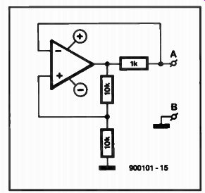
Fig. 5.
The circuit in Fig. 5 is constructed from an opamp and three resistors, while a negative resistance of-1 kO is simulated between terminals A and B. The operation may be checked by connecting a 4.7 kO resistor in series with terminals A and B. The total resistance measured with a standard ohmmeter is 3.7 kO which shows that the effect of a negative resistance can be measured. The value of it depends on the value of the output resistor used in the simulation circuit and the ratio of the other two resistors. Replacing the fixed 1 ka resistor by a variable type enables a wide range of negative resistance values to be obtained.
Another fairly simple method is to connect a conventional resistor in series with the negative resistance. In this example, this resistor should have a value not exceeding 1 kO to prevent the negative resistance from disappearing.
If a resistor (fixed or variable) greater than 1-kO is connected in parallel with terminals A and B, the negative resistance in creases (becomes more negative). The circuit in Fig. 5 is very suitable for experimenting with negative resistance.
When the circuit of Fig. 5 is translated into a practical design, a certain load, Rv, will exist between terminals A and B. This load has an effect on the operation of the circuit and its value must therefore be higher than the absolute value of -R, that is, in this circuit greater than 1 ka If the load across terminals A and B is always smaller than -R, the circuit is still us able, but the connections to the inputs of the opamp must be reversed (this maintains the required feedback). Although the circuit in principle be comes unstable only when the numerical values of Rv and -R are identical, it will be found in practice that it does not function satisfactorily when the values are close o another.
It will have become clear that the maximum potential drop across the negative resistance is highly dependent on the voltage source used for the simulation circuit. This also explains why the circuit of Fig. 3 does not generate a very high voltage, although it works satisfactorily: the supply voltage is not high enough.
The output characteristic of the opamp determines the maximum cur rent that can flow through the negative resistance. If larger currents are wanted, the output of the opamp must be provided with an additional stage. It is, of course, also possible to use an opamp that handles larger currents.
Applications
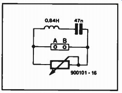
Fig. 6.

Fig. 7.
In practical electronics, negative resistance is used to compensate (ohmic) losses. A typical example is an LC circuit as shown in Fig. 6. The resonant frequency of this is 800 Hz and the Q-factor is 5.4. The value of Q is low, because it is heavily affected by the (loss) resistance of the inductor. It may be improved considerably by adding a variable negative resistance in parallel with the circuit. This is accomplished as shown: the fixed negative resistance is connected be tween A and B, and the potentiometer enables the losses caused by the resistance of the inductor to be compensated.
It is even possible to set the circuit into oscillation by making the negative resistance sufficiently large, that is, by reducing the value of the parallel resistance. The frequency range of the circuit will then be restricted, however, by the bandwidth of the simulation circuit.
Another application is the improvement of the control range of small d.c. motors. The rotating speed of such motors, especially at the low end of the range, is heavily dependent on the load moment. In fact, at a given point the motor just stops abruptly.
This behavior may be improved greatly with the aid of the circuit in Fig. 7, which contains not only a variable negative resistance but also a variable supply for the motor. Potentiometer P1 controls the rotating speed of the motor, while P2 sets the value of the negative resistance.
Experiments with a small d.c. motor showed that the deviation of the moment vs speed characteristic from the ideal could be improved by a factor of 2.7.
A final application is the use of a 3-ohm negative resistance to charge a battery.
Connected to a 12-V battery, the charging current is 4 A; connected to a 6-V battery, the charging current is 2 A. Such a negative-resistance charger has some peculiar properties: the connections to the battery terminals may be re versed with impunity and the short-circuit current amounts to nought.
Also see: In Quest of a Pangram