by Keith Brindley
This month we start to use integrated circuits, beginning with the 555 timer, which is widely used in teaching courses.
YOU'LL NEED a number of components to build the circuits this month, some of them you'll already have. but there are a few new ones, too. First, the resistors required are:
1 x 1k5
1 x 4k7
1 x 10k
Second, capacitors:
1 x 1n
2 x 10n
2 x 100n
1 x 1 u electrolytic
1 x 10u electrolytic
Power ratings, tolerances etc. of all these components are not critical, but the electrolytic capacitors should have a voltage rating of 9V or more.
Some other components you already have i.e., a switch, battery, battery connector, Verobloc, Banana meter, should all be close at hand, as well as some single-strand tinned copper wire. You are going to use the single-strand wire to make connections from point to point on the Verobloc, and as it's uninsulated this has to be done carefully, to prevent short circuits. Figure 1 shows the best method. Cut a short length of wire and hold it in the jaws of your long-nosed pliers. Bend the wire round the jaws to form a sharp right-angle in the wire. The tricky bit is next--judging the length of the connection you require, move the pliers along the wire and then bend the other end of the wire also at right angles round the other side of the jaws (Figure 2). If you remember that the grid of holes in the Verobloc are equidistantly spaced at 2.5mm (or a tenth of an inch if you're old-fashioned like me--what's an inch, Grandad?) then it becomes easier. A connection over two holes is 5mm long, over four holes is 10mm long etc.--you'll soon get the hang of it.
Now, holding the wire at the top, in the pliers, push it into the Verobloc as shown in Figure 3, until it lies flush on the surface of the Verobloc as in Figure 4.
No bother, eh? Even with a number of components in the Verobloc it is difficult to short circuit connections made this way.
Two other components you need are:
1 x 555 integrated circuit 1 x light emitting diode (any color)
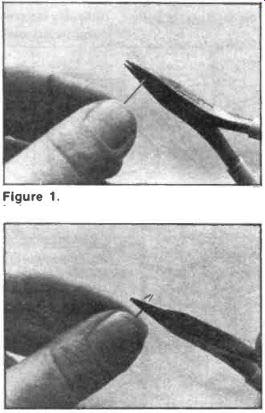
Figure 1. Take your short piece of wire between the jaws of your pliers ...
Figure 2.... and bend it carefully into two right angles, judging the length.
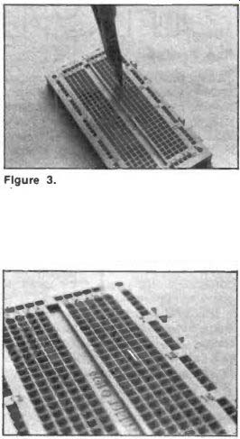
Figure 3. The wire link you have made should drop neatly into the Veroboard.
Figure 4. If the link is a good fit, it can be used over and over again in different positions.
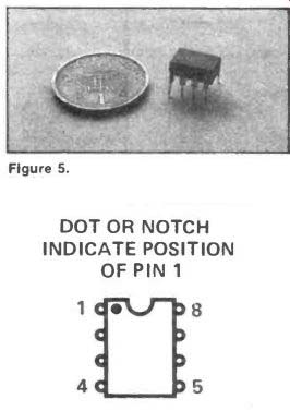
Figure 5. The 555, an 8 pin DIL timer IC, beside a UK one penny piece.
---------------- DOT OR NOTCH INDICATE POSITION OF PIN 1; Figure 6. A diagram of the normal con figuration for any IC: the dot marks pin 1 and the remaining pins run anti-clock wise.
----------------
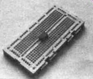
Figure 7. The IC mounted across the central divide in the Veroboard, which is designed to be the exact size.
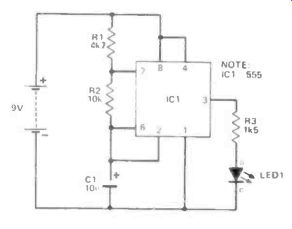
Figure 8. The circuit of the astable multivibrator circuit using the 555.
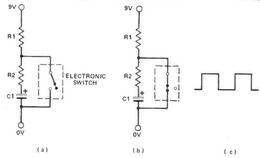
Figure 9. (a) shows a circuit equivalent to Figure 8 when the 555's switch
is off; (b) shows the circuit when the switch Is on; (c) shows the square wave
output signal.
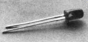
Figure 10. One of the most popular electronic components, the LED.
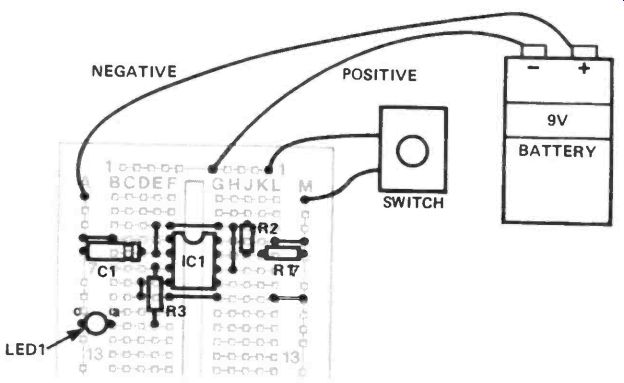
Figure 11. The Verobloc layout for the multivibrator circuit is shown in Figure
8--there is a photograph overleaf.
We've seen an integrated circuit (IC) before and we know what it looks like, but we've never used one before, so we'll take a closer look at the 555 now. It is an 8-pin dual-in-line (DIL) device and one is shown in Figure 5. Somewhere on its body is a notch or dot, which indicates the whereabouts of pin 1 of the IC as shown in Figure 6. The remainder of the pins are numbered in sequence in an anti-clockwise direction around the IC.
ICs should be inserted into a Verobloc across the breadboard's central bridged portion. Isn't it amazing that this portion is 7.5mm across (0.3in) and, hey presto, the rows of pins of the IC are about 7.5mm apart? It's as if the IC was made for the Verobloc! So the IC fits into the Verobloc something like that in Figure 7.
We'll look at the light emitting diode later.
If you remember, last month we took a close look at capacitors, how they charge and discharge, storing and releasing electrical energy. The first thing we shall do this month is use this principle to build a useful circuit called an oscillator. Then, in turn, we shall use the oscillator to show some more principles of capacitors. So, we've got a two-fold job to do now and there's an awful lot of work to get through--let's get started.
Figure 8 shows the circuit of the oscillator we're going to build. It's a common type of oscillator known as an astable multivibrator. The name arises because the output signal appears to oscillate (or vibrate) between two voltages, never resting at one voltage for more than just a short period of time (it is therefore unstable ie, astable). An astable multivibrator built from discrete ie, individual components, can be tricky to construct so we've opted to use an integrated circuit (the 555) as the oscillator's heart.
Inside the 555 is an electronic 'switch' which turns on when the voltage across it is approximately two-thirds the power supply voltage (about 6V in the circuit of Figure 8), and off when the voltage is less than one-third the power supply voltage (about 3V). Figure 9a shows an equivalent circuit to that of Figure 8 for the times during which the electronic switch of the 555 is off.
You should be able to work out that the capacitor C1 of the circuit is connected through resistors R1 and R2 to the positive power supply rail. The time constant of this part of the circuit is therefore given by:
ti = RC = (R1 + R2) C
When the voltage across the switch rises to about 6V, however, the switch turns on (as shown in Figure 9b), forming a short circuit across the capacitor and resistor, R2. The capacitor now discharges with a time constant given by:
T2 = R2 x C
Of course, when the discharging voltage across the switch falls to about 3V, the switch turns off again, and the capacitor charges up once more. The process repeats indefinitely, with the switch turning on and off at a rate determined by the two time constants. Because of this up and down effect such oscillators are often known as relaxation oscillators.
As you might expect the circuit integrated within the 555 is not just that simple and there are many other parts to it (one part, for example, converts charging and discharging exponential voltages into only two definite voltages--9V and 0V--so that the 555's output signal is a square wave, as shown in Figure 9c). But the basic idea of the astable multivibrator formed by a 555 is just as we've described here.
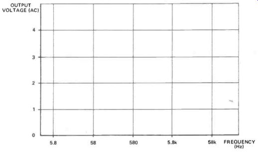
Figure 19 and Table 3 are for use with your results from the experiment with
the 10nF capacitor.
Table 4 Our results (C2 = 10n)
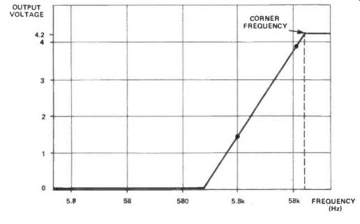
Figure 20 and Table 4 give our results In the same experiment.
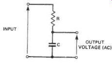
Figure 21. An AC voltage divider with the resistor and capacitor transposed.
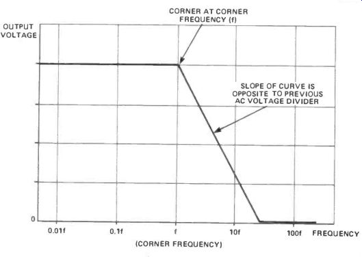
Figure 22. This graph shows the similarities and differences between this
circuit and that in Figure 13.
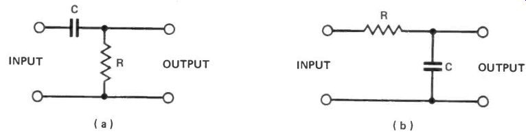
Figure 23. The AC divider sections of the circuits in Figure 21 and Figure
13.
Throwing Light On It
The 555 IC is one of only two new types of electronic component this circuit introduces you to. The other is a light emitting diode (LED) which is a type of indicator. One is shown in Figure 10. LEDs are polarized and so must be ...
---------------------
Table 2 and Figure 18 show our results which should be similar to yours (if not, you're wrong--we can't be wrong, can we?). The graph shows that the size of the output signal of the AC voltage divider is dependent on the frequency of the applied input signal. In particular, there are three clearly distinguishable sections to this graph, each relating to frequency.
First, above a certain frequency, known as the corner frequency, the output signal is constant and at its maximum.
Second, at low frequencies (close to 0 Hz) the output is zero.
Third, between these two sections the output signal varies in size depending on the applied input signal frequency.
Is this the same for all AC voltage dividers of the type shown in Figure 13? Well, let's repeat the experiment using a different capacitor for C2, to find out. Try a 10n capacitor and repeat the whole procedure, putting your results in Table 3 and Figure 19. Table 4 and Figure 20 show our results.
And yes, the graph is the same shape but is moved along the horizontal axis by an amount equivalent to a ten-fold increase in frequency (the capacitor was decreased in value by ten-fold, remember). A similar inverse relation ship is caused by changing the resistor value, too.
Frequency, capacitance and resistance are related in the AC voltage divider by the expression:
f = 1/ RC
where f is the corner frequency. For the first voltage divider, with a capacitance of 10n and a resistance of 1.5k, the corner frequency is:
f = 1 / 1500 x 100 x 10 ^9
= 6666 Hz
… which is more or less what we found in the experiment. In the second voltage divider, with a 10n capacitor, the corner frequency increases by ten to 66,666 Hz.
Remembering what we learned last month about resistors and capacitors in charging/discharging circuits, we can simplify the expression for corner frequency to:
f= T because the product RC is the time constant, T . This may be easier for you to remember.
An AC voltage divider can be constructed in a different way, as shown in Figure 21. Here the resistor and capacitor are transposed. What do you think the result will be? Well, the output signal size now decreases with increasing frequency--exactly the opposite effect of the AC voltage divider of Figure 13! All other aspects are the same, however: there is a constant section below a corner frequency, and a section where the output signal is zero, as shown in Figure 22. Once again the corner frequency is given by the expression:
1 = f RC 1
Filter Tips
The AC voltage dividers of Figures 13 and 23 are normally shown in a slightly different way, as in Figures 23a and b.
Due to the fact that they allow signals of some frequencies to pass through, while filtering out other signal frequencies, they are more commonly called filters.
The filter of Figure 23a is known as a high-pass filter--because it allows signal frequencies higher than its corner frequency to pass while filtering out signal frequencies lower than its corner frequency.
The filter of Figure 23b is a low-pass filter--yes, you've guessed it--because it passes signals with frequencies below its corner frequency, while filtering out higher frequency signals.
Filters are quite useful in a number of areas of electronics. The most obvious example of a low-pass filter is probably the scratch filter sometimes seen on stereo systems. Scratches and surface noise when a record is played, or tape hiss when a cassette tape is played, consist of quite high frequencies; the scratch filter merely filters out these frequencies, leaving the music relatively noise free.
Bass and treble controls of an amplifier are also examples of high- and low-pass filters: a bit more complex than the simple ones we've looked at here but following the same general principles.
We'll also see many more examples of filters along the way.
Figure 23. The AC divider sections of the circuits in Figure 21 and Figure
13.
And that's about it for this month. You can try a few experiments of your own with filters if you want. Just remember that whenever you use your meter to measure voltage across a resistor in a filter, the meter resistance affects the actual value of resistance and can thus drastically affect the reading.
Quiz
1) a b d e 2) a b d e
A signal of frequency 1 kHz is applied to a low-pass filter with a corner frequency of 10 kHz. What happens?
The output signal is one-tenth the input signal
The output signal is larger than the input signal
There is no output signal The output signal is identical to the input signal
All of these
A high-pass filter consisting of a 10k resistor and an unknown capacitor has a corner frequency of 100 Hz. What is the value of the capacitor?
1n 10n 100n 1000n 1u
-----------------------
....inserted into circuit the right way round.
All LEDs have an anode (which goes to the more positive side of the circuit) and cathode (which goes to the more negative side). Generally, but not always, the anode and cathode of an LED are identified by the lengths of the component leads--the cathode is the longer of the two.
The complete circuit's Verobloc layout is shown in Figure 11, and a photograph of the circuit is in Figure 12.
Build it and see what happens.
When you turn on, you should find that the LED flashes on and off, quite rapidly (about five or six times a second, actually). This means your circuit is working correctly. If it doesn't work check polarity of all polarized components: the battery, IC, LED and capacitor.
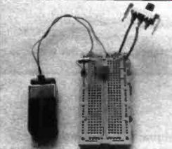
Figure 12. The multivibrator circuit built up on Verobloc.
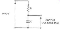
Figure 13. A voltage divider--but with a capacitor.
Ouch, That Hertz.
We can calculate the rate at which the LED flashes, more accurately, from formulae relating to the 555. A quick study of the squarewave output shows that it consists of a higher voltage for a time (which we can call T1) and a lower voltage for a time (which we will call T2).
Now, T1 is given by:
T1 = 0.7 T 2 and T2 is given by:
T2 = 0.7 t 2
So, the time for the whole period of the squarewave is:
Ti + 12 = 0.7( 11 + 2) and as the frequency of a waveform is the inverse of its period we may calculate the waveform's frequency as:
f= 1
0.7( + 12)
Earlier, we defined the two time constants, T and T 2, as functions of the capacitor and the two resistors, and so by substituting them into the above formula, we can calculate the frequency as:
1 f
= 0 7C(R1 + 2R2)
So, the frequency of the output signal of the circuit of Figure 8 is:
f
0.7 x 10 x 10'6 x (4700 + 20,000)
= 5.8 cycles per second or, more correctly speaking:
= 5.8Hertz (shortened to 5.8Hz)
Equation 1 is quite important really, because it shows that the frequency of the signal is inversely proportional to the capacitance. If we decrease the value of the capacitor we will increase the frequency. We can test this by taking out the 10u capacitor and putting in a 1u capacitor. Now, the LED flashes so quickly (about 58 times a second) that your eye can't even detect it is flashing and it appears to be always on. If you replace the capacitor with one of a value of say 100u the LED with flash only very slowly.
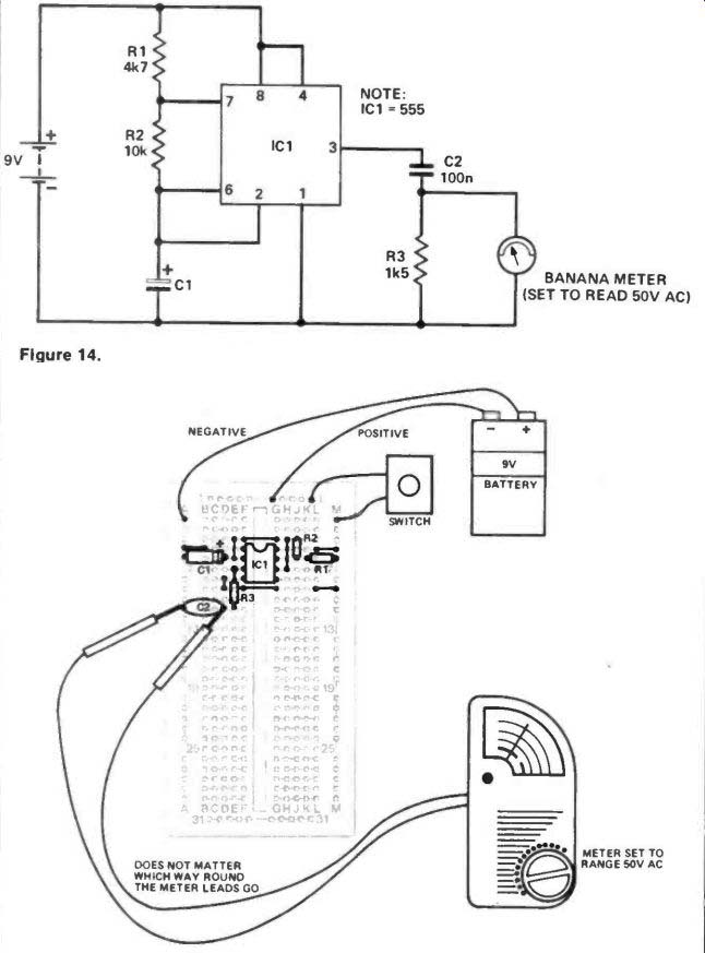
Figure 14. A circuit combining the astable multivibrator and the circuit In
Figure 13.
Figure 15. The Vero layout of the circuit in Figure 14. It is the same as that in Figure 11, with a capacitor in place of the LED.
Now, let's stop and think about what we have just done. Basically we've used a capacitor in precisely the ways we looked at last month--to charge and discharge with electrical energy so that the voltage across the capacitor goes up and down at the same time. True, in the experiments last month you were the switch, whereas this month an IC has taken your place. But the principle--charging and discharging a capacitor is the same.
The current which enters the capacitor to charge it, then leaves the capacitor to discharge it, is direct current because it comes from a 9VDC battery. However, if we look at the output signal (Figure 9c) we can see that the signal alternates between two levels.
Looked at in this way, the astable multi--vibrator is a DC-to-AC converter. And that is going to be useful in our next experiment, where we look at the way capacitors are affected by AC. The circuit we shall look at is shown in Figure 13 and is very simple, but it'll do nicely, thank you. It should remind you of a similar circuit we have already looked at; the voltage divider, only one of the two resistors of the voltage divider has been replaced by a capacitor. Like an ordinary voltage divider the circuit has an input and an output. What we're going to attempt to do in the experiment is to measure the output signal when the input signal is supplied from our astable multivibrator.
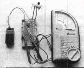
Figure 16. A photo of the circuit in Figure 15.
Figure 14 shows the whole circuit of the experiment and Figure 15 shows the
Table 1 Results when capacitor C2 is 100n Value of C1 Calculated Measured voltage frequency
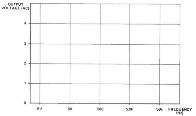
Figure 17. A blank graph on which you can plot your experimental results.
Use Table 1 above as well.
Table 2 Our results (C2 ± 10002 Value of C1 Calculated Measured voltage frequency
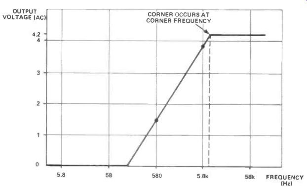
Figure 18 and Table 2 show our own experimental results.
Verobloc layout, while Figure 16 shows a photograph of the set-up before switch-on. The procedure for the experiment is pretty straightforward: measure the output voltage of the AC voltage divider when a number of different frequencies are generated by the astable multivibrator, then tabulate and plot these results on a graph. Things really couldn't be easier. Table 1 is the table to fill in as you obtain your results and Figure 17 is marked out in a suitable grid to plot your graph. To change the astable multivibrator's frequency, it is only necessary to change capacitor-C1.
Increasing it ten-fold decreases the frequency by a factor of ten; decreasing the capacitor value by ten increases the frequency ten-fold. Five different values of capacitor therefore give an adequate range of frequencies.
As you do the experiment you'll find that only quite low voltages are measured (up to about 4VAC) and as the Banana meter's lowest AC range is 50V, you may not achieve the level of accuracy you would normally desire, but the results will be OK, nevertheless.
3) A low-pass filter consisting of a 1u capacitor and an unknown resistor has a corner frequency of 100Hz. What is the value of the resistor? a 10k b 1k c 100k d All of these e It makes no difference f d and e g None of these
4) In a circuit similar to that in Figure 8, resistor R1 is 10K, resistor R2 is 100k, and capacitor C1 is 10n. The output frequency of the astable multivibrator is:
a. a squarewave; b. about 680Hz c too fast to see the LED flashing d a and b e c and d f
None of these
Answers to last month's quiz:
la; 2f, 3c; 4c: 5c
Glossary of Important Terms
astable multivibrator an oscillator whose output is a squarewave corner frequency the frequency at which a signal size changes from one slope to another, when viewed as a graph of size against frequency. In the simple filter circuits in this article, the corner frequency, f, is given by the expression:
1 f RC
discrete--term implying a circuit built up from individual components.
filter--a circuit which allows signal of certain frequencies to pass through unaltered, while preventing passage of other signal frequencies.
high-pass filter--a circuit which allows signals of frequencies higher than the corner frequency to pass through unaltered, while preventing signals of frequencies lower than this from passing.
low-pass filter--a circuit which allows the passage of signals with frequencies lower than the corner frequency. but prevents the passage of signals with frequencies higher than this.
oscillator--a circuit which produces an output signal of a repetitive form.
relaxation oscillator--an oscillator relying on the principle of a charging and discharging capacitor.
squarewave--a signal which oscillates between two fixed voltages.
Also see: REVIEW: BOX OF TRICKS -- Classy cases for prestigious projects.