In the second part of our feature on soldering, we cover faulty joints, double-sided boards and desoldering techniques.
-by Marcus Smith
Bad Joints
As I mentioned last month the main cause of a bad connection is dirt on the PCB or components. Under- or over heated solder is another cause to watch out for.
If the joint has a fault, the solder will tend to interface with the metal at a convex angle, even to the extent of forming a ball around the joint.
Poor wetting causes the solder to settle in blobs around the joint. If the this happens, try reheating the joint more thoroughly, and see what happens.
Don't add more solder, as this may make the joint look correct while hiding a poor contract. If the joint refuses to settle right the second time, desolder and clean the surfaces. If the joint takes on a crystalline appearance, the solder has overheated: desolder and clean.
If the solder forms definite balls around the joint and on the tracks, the joint needs desoldering and de-tarnishing right away.
If the joint appears to settle properly, and then withdraws into a blob, you have again a tarnish problem, and the joints need desoldering and cleaning.
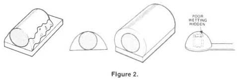
Figure 1. With poor wetting, caused by dirt on the connections, the solder
forms a convex angle or 'bulge' around the joint, and may break up into blobs.
Figure 2. The result of adding extra solder to a poorly-wetted joint is a poorly wetted joint with extra solder on it. Unsolder start again!
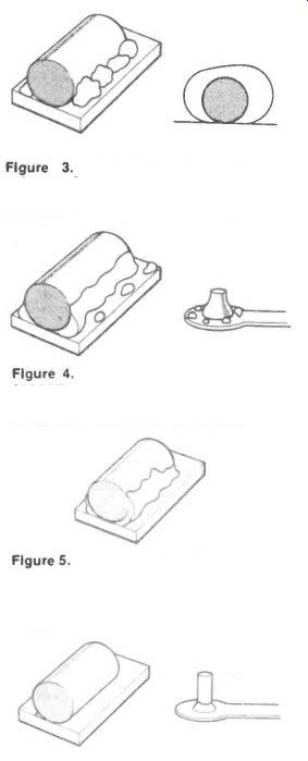
Figure 3. Tarnished joints cause an extreme form of non-wetting. If this happens,
unsolder the joint and clean it with abrasive before re-soldering.
Figure 4. 'De-wetting' is when the solder appears to settle correctly, and then withdraws into blobs and flat spots on the surface. Treat as for non-wetting.
Figure 5. A steep, straight angle is caused when the solder is under-heated. The solder is brittle and may be levered off. The cure is to re-heat the joint to the correct temperature.
Figure 6. Too little solder, even if applied correctly, makes a joint which is not strong enough to stand up normal to stresses and will fracture easily. Add more solder.
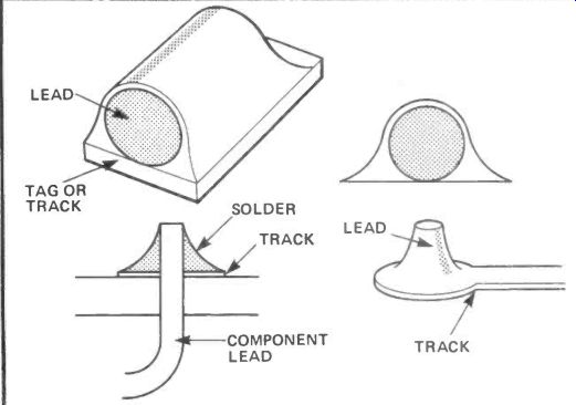
----------- A quick revision on the appearance of a good joint: the solder
lies at a gentle concave angle with the joint, is smooth and normally shiny
in appearance and covers the joint evenly without concealing it. Leads should
be cut off about 2mm above the board, either before soldering, otherwise giving
the solder time to set firmly first. Under-heating the joint, or dirt and tarnish
on the connections, are the main causes of bad joints. Disturbing the joint
before it has cooled, or cooling it artificially, can cause cracks.
Dry Joints
The most notorious form of bad joint is the 'dry' joint. Dry joints generally take the blame if a project doesn't work the first time. A dry joint is not one which hasn't wetted properly, despite its name, but one which has been made too cool, or been disturbed while setting. It is tricky, because it may work at first, but is brittle, so that any slight disturbance of the board will disconnect it. Dry joints look much like good joints, but tend to lie at a steeper angle, and may have a frosty crystalline appearance.
Thorough reheating usually cures a dry joint, but inspect it thoroughly. If solder is reheated too often, a similar kind of breakdown can occur, caused by the introduction of dirt, vaporization of flux, overheating the solder, etc. Dry joints are sometimes (and more accurately) called 'cold' or 'grey' joints.
The same conditions which cause dry joints can cause little pointy bits of solder, called Icicles, to form on joints as the iron is removed. Follow the same procedure as for dry joints.
Care, caution and clean components--and practice--is all that is needed to master the art of soldering.
-------------------
Double Sided PCBs
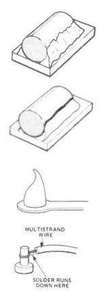
(Above) a correct solder joint for a connection through a double-sided board (below) not enough solder has settled in the connecting hole, and the joint will be weak.
On double-sided PCBs, the usual rules apply, with the proviso that if there are plated-through holes, there must be enough solder to fill the hole. The solder should run into the plated holes easily, but a little extra heat and solder is needed.
For unplated holes, solder the component on whichever side of the board it needs to make contact with a track. You may find yourself soldering from the component side of the board.
This is not a problem, but take care not to put the iron onto the body of the component. If this seems inevitable, mount the component on longer leads (you haven't cut the leads yet, have you?) to give yourself more working room.
You may be using PCB pins. Make sure they are firmly attached, on both sides of the board if necessary. When attaching a component to a PCB pin, just take the lead in a U-turn around the pin.
More wrapping than this will make a clumsy joint, and one which is hard to desolder.
--------------------
Desoldering
Desoldering is an important thing to bear in mind when assembling a board.
You may need to do a repair, or alter a component value.
Melting the solder is simple. If you can touch the iron to both leads at once, you can lift the component out quickly with your fingers or a pair of fine pliers.
Bending the leads to lift out one lead at a time is also reasonable, but be careful if you want to re-use the component.
In more tricky desoldering situations, use a solder sucker--a cheap and useful tool--to remove the molten solder before you work out the component. The remarks higher up about flicking also apply to emptying solder suckers! Desoldering braid can also be used to remove solder.
If you are removing an IC, it is essential to remove the excess solder first to avoid damaging the pins. In the case of a PTH board, it is safer to cut the pins of the IC socket, or even of cheap ICs, than to risk overheating or tearing the through plating.
Figure
7. A 'dry' or 'cold' joint may have a good shape but has a grainy appearance.
Re-heat without adding extra solder. If the joint does not form properly after
a second try, desolder, clean the joint and start again.
Figure 8. Another result of under-heating the joint may be a resin bond. A thin translucent layer of resin can be seen between the solder and the joint, preventing electrical contact. Treat as for a dry joint.
Figure 9. Small points which form on the solder when the iron is withdrawn are called 'icicles'. Treat as for a dry joint if necessary, but if the joint seems otherwise sound, the odd icicle does no harm.
MULTISTRAND WIRE SOLDER RUNS DOWN HERE
Figure 10. 'Wicking' is a fault caused when solder runs down multistrand wire from the joint. This makes the wire brittle, and it may later break. Prevention: make sure stranded wire is pointing 'uphill' when soldering.
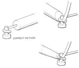
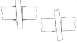
Figure 11. The right way of attaching a component to a PCB pin. Do not wind
or cross the component lead.
Figure 12. Make sure that the bit you are using is large enough to heat the whole joint. The solder may break up if under-heated, or it may form a dry joint.
Also see: METERS, METERS, METERS -- Thirty-one multimeters assessed in all price ranges.