by R. A. Penfold
Testing radio equipment using a signal tracer usually results in the fault being quickly and easily located. The basic technique is to inject a signal into the input of the faulty equipment, either from a signal generator or an ordinary program source, and then test to see if this signal is present at various points in the circuit, working from the input through to the output. When the signal can no longer be located, the fault either lies in the stage just tested or in the circuitry immediately before this. Visual checks together with voltage and component tests are then used to discover the precise nature of the fault.
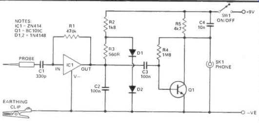
This simple circuit is a sensitive RF signal tracer that operates well over the medium wave and long wave bands as well as at the popular broadcast receiver intermediate frequencies around 455 to 470kHz. It also seems to work quite well at SW frequencies up to several megahertz. The circuit is built around the popular TRF radio IC, the ZN414, IC1.
This would normally have a tuned circuit at the input to provide frequency selectivity, but in this application it is used as a broadband amplifier with C1 being used to couple the input signal to the input terminal of the device. Resistor R1 biases IC1, while R2, D1, and D2 provide it with a stabilized supply potential of about 1.3 volts. Resistor R3 and capacitor C2 are the load resistor and RF filter capacitor respectively for the detector and automatic gain control stages of IC1.
Capacitor C3 couples the demodulated audio signal at the output of 101 to the input of a high gain common emitter amplifier formed by Q1.
Capacitor C4 provides RF filtering at the output of this stage and helps to avoid instability due to stray high frequency feedback. The output is taken to a crystal earphone, and other types are not suitable for use with this unit. The current consumption of the circuit is only about 5mA or so.
The circuit has extremely high sensitivity and it is therefore advisable to house the circuit in a small metal case which is earthed to the negative supply so that it screens the circuitry from RF signals within the broad passband of the unit. The probe can merely consist of a long M3 or M4 screw fitted to the case but insulated from it.
Also see: News