by DAN BECKER
Learn the fundamentals of crystal resonators how and why they work in oscillators and frequency standards.
CRYSTAL RESONATORS ARE STILL the most widely used components for converting electrical energy into precise frequencies for communications and timing. Among the many instruments, products, and systems that depend on crystals to produce their precise, stable frequencies are frequency counters, radio transmitters, electronic navigation systems (transmitters and receivers), TV sets, and VCR's.
This article reviews the fundamentals of crystal resonators.
Because of their utility and low cost, it emphasizes those made from quartz--how and why they work. The distortion of crystal resonators by the application of an alternating voltage across its faces is explained by the piezoelectric effect. Although synthetically produced quartz is still the leading material for manufacturing piezoelectric resonators, many other natural and man-made materials exhibit similar properties.
The information presented here is an introduction to the second installment in this series addressing the design and application of crystal-controlled oscillators such as the Colpitts, Pierce, and Butler. These oscillators, originally designed as vacuum-tube oscillators, have been adapted to transistors, and they include crystal resonators.
Armed with the information well present on the mechanical and electrical properties of crystal resonators, you'll have a better understanding of how to purchase and use low-cost crystals in your experiments or electronic projects.
Properties of crystals
The starting point in this subject is crystallography, the study of the form, structure, properties, and classification of crystals. This specialized subject linking physics, chemistry, geology, and mechanical engineering, is usually touched on only briefly in formal electronics engineering courses. With the wealth of subject matter to cover, instructors rarely say much about crystal resonators except to note that they are readily available components and can be viewed as electrically equivalent to high-Q LCR tank circuits.
Crystallography deals with lattices, bonding, and the behavior of slices that have been cut at various angles with respect to the crystal's axes. The mechanical properties of crystal lattices permit the important piezoelectric effect. Sections of crystal blanks that have been cut and polished according to well known rules vibrate when alternating voltages are applied across their faces.
The dimensions of the crystal slice-particularly its thickness and where and how it was cut from the blank determine its electrical and mechanical properties. Other factors are the form of the electrodes and how the crystal is supported.
A resonant crystal's behavior can be simulated as either a parallel or series tank circuit with capacitors, an inductor, and a resistor. As tank circuits, crystals have figures of merit or Q's that are orders of magnitude superior to those of discrete-component resonant circuits.
Piezoelectric effect
To understand how and why a crystal resonates as a tank circuit, it is necessary to understand the piezoelectric effect.
Occurring in both man-made and natural crystals, there are two reciprocal modes to this effect. The first, as shown in Fig. 1-a, is the generation of a voltage between the opposite faces of a piezoelectric crystal as a result of stressing the crystal along its longitudinal axis.
The stress can take the form of squeezing (compression), stretching (tension), twisting (torsion), or shearing. In fact, if the crystal is stressed periodically, the output voltage will be alternating. This effect can be seen by observing needle swing on a high-impedance voltmeter or as an alternating wave on an oscilloscope.
The second mode, shown in Fig.1-b, is the mechanical deformation of the crystal caused by the application of a voltage across the opposite faces of the crystal. The degree of deformation will depend on the characteristics of the drive signal as well as those of the crystal cut.
The application of an AC signal will produce periodic longitudinal, shearing or flexural motion.
In Fig. 1 the electrodes make the electrical connection to an external drive or output circuit.
Here the thickness of the electrodes has been exaggerated; in practical resonators they are thin films of metal deposited on the opposing faces of the thinnest section of crystal, similar to the plates of a ceramic-disc capacitor.
The piezoelectric mode shown in Fig. 1-a is applied in crystal microphones, strain gauges, and receiving elements in depth sounders, for example.
In those applications they are known as transducers. By contrast, the applications for the mode illustrated in Fig. 1-b include frequency standards for telecommunications, as frequency generators, and as time standards in watches, clocks and timebase generators. That mode is also applied in ultrasound generators and cleaning machines, and the transmitting elements of depth sounders, where they are also known as transducers. In depth sounders and ultrasonic diagnostic equipment, the transducer can function both as a transmitting and receiving element.
The piezoelectric effect is exhibited by many natural and man-made crystals; the most important natural crystals are quartz, Rochelle salt, and tourmaline. There are also many man-made piezoelectric elements such as ADP, EDT, and DKT that are used as filters and transducers. However, synthetic quartz is still the most widely used material for oscillator frequency control because of its permanence, low temperature coefficient, and high mechanical Q.
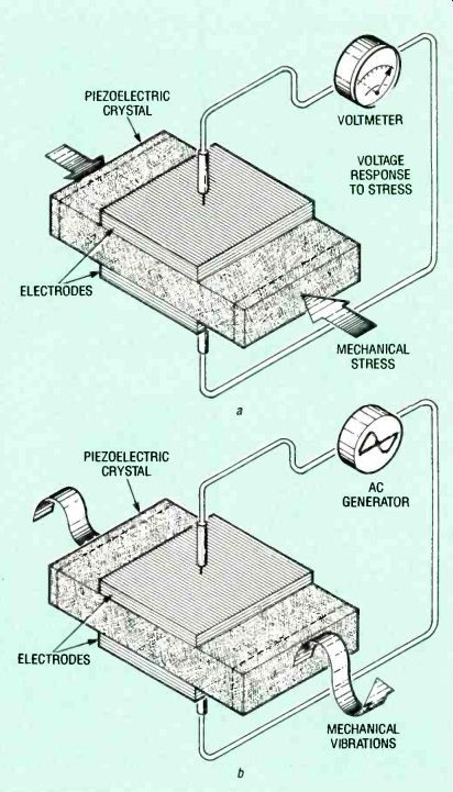
FIG. 1--THE PIEZOELECTRIC EFFECT IS RECIPROCAL. Stressing the crystal
will generate a voltage which causes the meter needle to jump, a, and
applying an alternating electrical signal across the electrodes will
cause the crystal to be mechanically deformed, b.
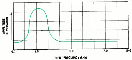
FIG. 2-A CRYSTAL'S RESONANT FREQUENCY can be determined by sweeping
the input frequency until an amplitude peak representing mechanical resonance
is seen on an oscilloscope.
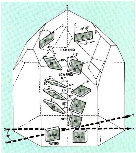
FIG. 3 CRYSTAL SLICES ARE CUT FROM A QUARTZ blank at different angles
with respect to the axes to yield different mechanical and electrical
characteristics.
Crystal resonance
The mechanical resonant frequency of a crystal can be determined by applying an alternating voltage from a signal generator (whose range extends over the likely resonance frequency) across the crystal faces.
As shown graphically in Fig. 2, the applied frequency is slowly changed while observing the amplitude of the trace on an oscilloscope, the resonant frequency of a piezoelectric crystal under test can be found visually.
The mechanical resonance of the crystal shown occurs at about 2.2 kHz.
The mechanical vibrations within a piezoelectric crystal slice are called bulk acoustic waves (BAW's). In general, the thinner (and smaller) the crystal slice, the more rapid will be the mechanical vibrations and the higher will be its resonant frequency.
Figure 3 is a perspective drawing showing various crystal cuts from a quartz blank. The orientation of the cut with respect to the blank's major crystallographic axes strongly influences its piezoelectric properties and temperature stability.
There are three principal crystal axes: X, Y, and Z (known as the optical axis). Figure 3 shows some of the most popular cuts and how they are oriented with respect to each other. They are designated by two letter symbols. Examples are AT, BT, CT, DT, ET, AC, GT, and JT. The angles shown relate the edges of the cuts to the blank's principal axes.
Each cut has special characteristics. The AT cut is the most popular for high frequency and very-high frequency crystal resonators. The AT cut exhibits high frequency shear and produces a fundamental in the 800 kHz to 25 MHz range. However, it overtones (to be discussed later) permit operation up to 200 MHz. The CT and DT cuts exhibit low frequency shear and are most useful in the 100-to 500-kHz range. The MT cut vibrates longitudinally and is useful in the 50to 100-kHz range while the NT cut flexes and has a useful range under 50 kHz.
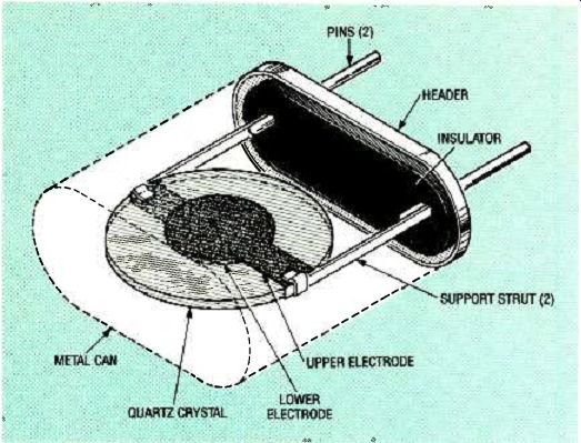
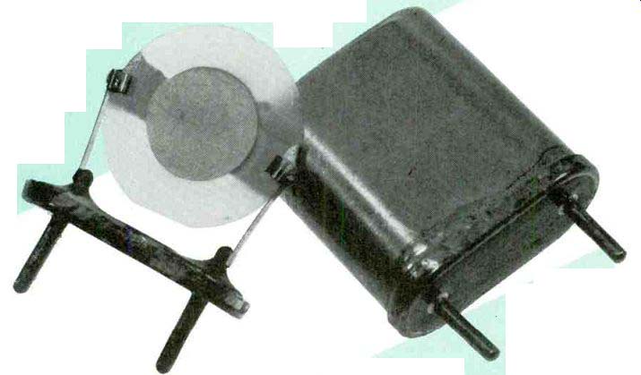
FIG. 4-A QUARTZ-CRYSTAL RESONATOR with its case removed. The silvered
electrodes are on opposite sides of crystal disk and the disk is supported
at its nodal points.
Practical resonators
Figure 4 is a drawing of a typical crystal resonator with its protective case or can removed.
The crystal resonator is sliced, cut, and polished as a disk. It has one deposited metal electrode on each face, about 1000 angstroms thick. Electrode metal can be gold, silver, aluminum or other suitable metal.
The resonator is supported on each edge at nodal points, places where the support will provide least damping of the vibrating crystal. Flexible support struts bonded to each side of the crystal connect the electrodes to base pins.
Crystal manufacturers refer to the complete assembly of crystal, support, and case as a holder. The insulated pins in the base of the holder are for external electrical connections.
The flat metal case is either soldered or welded to the base to form a hermetic seal. Sealing is typically done in a vacuum chamber which might also contain an inert gas such as nitrogen to provide additional protection for the crystal against contamination. It is essential that all moisture be removed from the case. The removal of air from the holder reduces the crystal's mechanical load and affects its resonant frequency.
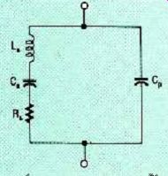
FIG. 5--IN AN EQUIVALENT CIRCUIT FOR A CRYSTAL resonator, L C5, and
R, represent the crystal, and Cp represents the capacitance of electrodes
and holder.
Series and parallel resonance Crystal resonators can be modeled near resonance with the equivalent circuit shown in Fig. 5. The series combination Ls, Cs, and Rs represent the electrical equivalent of the vibrational characteristics of the crystal by itself. The inductance Ls is the electrical equivalent of the crystal mass that is effective in vibration, Cs is the mechanical equivalent of the effective mechanical compliance, and Rs represents the electrical equivalent of mechanical friction.
This equivalent circuit is modified, however, when the crystal is mounted in the crystal holder. As a result, the equivalent circuit of the mounted crystal is the parallel circuit shown in Fig. 5. Capacitor Cp represents the electrostatic capacitance between the crystal electrodes and the stray capacitance associated with the holder when the crystal is not vibrating.
At series resonance, the reactances of Cs and Ls cancel out, leaving resistor Rs and a small amount of capacitive reactance from static capacitor Cp. At a frequency slightly above series resonance, fs, the reactance of Cp cancels out and the crystal looks resistive. The value of this resistance is called the equivalent series resistance. Manufacturers usually specify only a maximum value of ESR because precise values are seldom needed in oscillator design.
Crystals made to operate at series resonance are called series-resonance crystals.
A series-tuned circuit is capacitive below its series-resonant frequency fs and inductive above it. The series resonant frequency is given by: 1 fs = 2n/L,Cs At some frequency fp, which is higher than fs, the crystal will act as a parallel-tuned circuit because the now inductive series branch resonates with C1,. Crystal resonators made to oscillate above series resonance are called parallel resonance crystals or load-resonance crystals. The parallel resonant frequency is:
1 f P 27r. JLSC C = CSCP Cs + CP
… where crystal resonators intended for parallel resonance operation include a specification called the load capacitance, abbreviated CL. Typically 10 to 100 picofarads, it is called load capacitance because it is the capacitance value that the oscillator circuit presents to the crystal, that is, the crystal's load.
Load capacitance can be approximated as a 10 to 100 picofarad capacitor in series with a series resonant circuit (the crystal). If the load capacitance is decreased, the resonant frequency of the total circuit (crystal plus load capacitor) will increase. As frequency increases, the crystal becomes more and more inductive. Most oscillator circuits call for an inductive crystal resonator.
Therefore, parallel resonance crystals are very popular.
Series vs. parallel.
In an oscillator circuit a parallel resonance crystal is usually more stable than a series-resonance crystal. The parallel-resonance crystal's change in inductive reactance per change in frequency (LX/Af) is greater above series resonance than at series resonance. This sharpens the tuning of the feedback network. Therefore, noise signals higher or lower than the resonant frequency are quickly damped out. This prevents off-frequency oscillation.
Figure 6 summarizes crystal resonator characteristics by plotting reactance vs. frequency. In the parallel resonance region, the magnitude of the crystal's resistance increases above its ESR value. Manufacturers usually refer to this as the crystal's maximum resistance with load capacitance or, the crystal's load resistance.
The frequency at which the inductive reactance abruptly changes to capacitive reactance (and resistance approaches a maximum), is called anti-resonance. It is not specified in data sheets for most oscillator applications.
Table 1 gives typical values for a selection of crystal resonators.
The columns headed Cs, Ls, and Rs are the series values and Cp represents parallel capacitance.
The CL column is load capacitance and the RL column is load resistance.
TABLE 1 TYPICAL VALUES FOR A CRYSTAL EQUIVALENT CIRCUIT
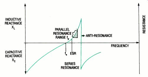
FIG. 6 CHARACTERISTICS OF CRYSTAL RESONATORS: parallel resonance, and
series resonance are shown.
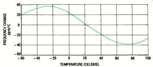
FIG. 7-Plot of frequency change with respect to temperature for a typical
AT-cut crystal resonator.
so 80 100
Other characteristics.
The relationship between a quartz crystal's thickness and resonant frequency is expressed as h = 65.5/íR, where h is the thickness in inches, and fR is the resonant frequency in kilohertz. This formula says that for high frequency oscillation, the quartz wafer must be very thin. This fact makes it difficult to manufacture crystal resonators with fundamental frequencies much above 30 MHz because the crystal is so thin that it is exceptionally fragile and conventional cutting and polishing could result in high production cost.
Some crystal resonator manufacturers get around this problem by using chemical etching to achieve thinner slices of quartz. This has made it possible to achieve fundamental frequencies up to about 350 MHz, but this process is more costly and it increases the cost of those resonators.
Resonant frequencies higher than 30 MHz have been obtained by making use of harmonically related vibrations that occur simultaneously with the fundamental vibration. The harmonics are odd multiples of the fundamental (3, 5, 7 and 9) and they are referred to as overtones because they are not true harmonics. The tradeoff is that special provisions must be made in oscillator circuits to enhance those overtone frequencies.
Manufacturers can process a crystal so that one overtone is stronger than the others. Typically, overtone crystals are available for the 3rd, 5th, 7th, or 9th mode of vibration. Thus a 30-MHz, third-overtone crystal actually has a 10-MHz fundamental, but the crystal is cut to enhance its third mode. Low-cost overtone crystals with frequencies up to 200 MHz are available as standard commercial products. More expensive chemically-milled resonators can have overtones up to about 500 MHz.
Temperature stability
A crystal's resonant frequency changes with temperature.
Crystal manufacturers express temperature-related changes in parts per million per degree Celsius ( ppm/°C). Figure 7 is a plot of resonant frequency change with temperature for a typical low-cost AT-cut crystal.
When a desired operating temperature is specified, a manufacturer fabricates the crystal so that its optimum stability point (zero ppm/°C on Fig. 7) corresponds to that temperature.
For low cost units, this is 25 °C. To find the maximum frequency change, locate the ppm/°C value corresponding to the given temperature. Next, multiply ppm by the nominal operating frequency (in megahertz). For example, at-20 °C, a crystal can have a + 38 ppm/°C rating. If its resonant frequency is specified to be 10 MHz (at 25 °C), its resonant frequency will increase by 380 Hz when its temperature drops to-20 °C (38 ppm X 10 MHz). For most practical circuits this represents a minor frequency change. However, if strict frequency control is required in any application, a crystal oven or temperature-compensated oscillator (TCXO) should be included.
Calibration tolerance.
A crystal's true frequency might not be exactly the same as the value stamped on its case. The error depends upon the crystal's calibration tolerance. Moreover, its calibration tolerance is specified at one specific temperature, usually 25 °C. For example, expect a 10-MHz crystal with a ± 25 ppm/°C calibration tolerance to have a resonant frequency within ± 250 Hz of 10 MHz when operating at 25 °C. Aging g is a gradual change in a crystal's resonant frequency with respect to time. It is usually specified in parts per million per year (ppm/year). Typical values range from 3 to 10 ppm/ year. For example, a 10-MHz crystal with an aging rate of 10 ppm/year can change by 100 hertz per year. One cause of aging is the redistribution of particles of quartz and embedded grinding compound that were not removed by careful cleaning.
These microscopic materials remain within the holder after hermetic sealing and are redistributed as a result of resonator vibration. Thus aging is directly affected by the power input or drive level.
In addition, slow leaks in the hermetic seal can allow air, moisture and contaminants into the case which will shift the resonant frequency. Stresses on the electrodes and changes in atmospheric pressure that flex the outer walls of the case can also contribute to the aging of a crystal.
Power dissipation.
As with any object that is vibrating at its resonant frequency, the vibrations can quickly build to a destructive level. lb maintain temperature stability and to avoid damaging the crystal resonator, each crystal has a recommended maximum drive level. Typical maximum values range from 5 milliwatts at low frequencies to 0.1 milliwatt at high frequencies because high-frequency crystals are thinner than low frequency crystals.
Standard holders
The holders were standardized by a military specification years ago, and they are still referred to as HC numbers (for HC-XX/U) to identify resonator type and size. Crystal resonators are available from stock with resonant frequencies from about 70 kHz to 200 MHz. Specials can be ordered as custom items. We wish to acknowledge the assistance of Royden Freeland of International Crystal Mfg., Co. Oklahoma City, OK, in checking this manuscript for accuracy.
R-E
Also see: Crystal Oscillators -- Part 2