LAST MONTH WE TALKED ABOUT how the Air Hop system works and went into detail on how optics help increase range. So let's get to work building the system.
Board construction
As you already know, the Air Hop is made from three separate sections, on three separate PC boards. We've provided the foil patterns for the boards in case you want to make your own. The parts placement diagram for the transmitter board is shown in Fig. 9, the optical amplifier board in Fig. 10, and the FM demodulator board in Fig. 11. In Fig. 10, notice that there are three holes for D1, which allow you to mount the PIN diode facing the front of the board regardless of which PIN diode you use. Also in Fig. 10, as mentioned before, R4 and R5 make up one low-capacitance resistor-solder one lead of each resistor together above the board and mount the other two leads normally. Note that each board has a separate parts list, so be sure to put the right parts on the right board! Mechanical construction The physical construction of an optical communications system is just as important as the electrical circuitry. The most obvious problem is keeping the optics in alignment. However, there is another problem with a system that contains a phase-locked loop.
Remember that a phase-locked loop (PLL) contains a voltage-controlled oscillator, or VCO. The PLL compares its VCO with the incoming signal and produces a correction voltage which turns out to be the recovered audio. Even if no signal is being produced by the receiver, the internal oscillator is running and herein lies the problem: If the VCO isn't shielded, or if the power supply isn't properly decoupled, some of the VCO energy can be coupled into the front end of the receiver. That "leakage" signal is amplified by the receiver and is fed back to the phase-locked loop. Because it's the original signal. the loop locks to itself!
When the input from the receiver exceeds the leakage signal, the loop locks to the real signal and the circuit works well. However the new signal must be larger than the leakage signal meaning that the receiver could be made more sensitive if the leakage were eliminated.
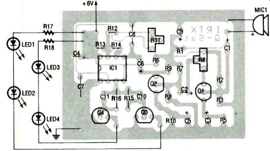
FIG. 9--FM TRANSMITTER parts-placement diagram.
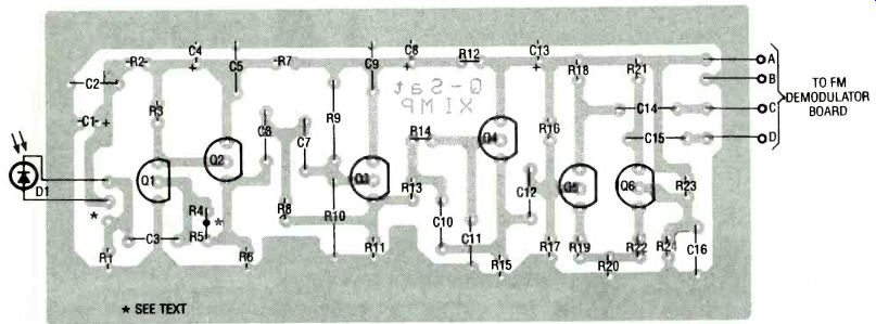
FIG. 10--OPTICAL AMPLIFIER parts-placement diagram. There are three holes
for D1 to accommodate different PIN diodes. Resistors R4 and R5
are wired in series and installed as one resistor.
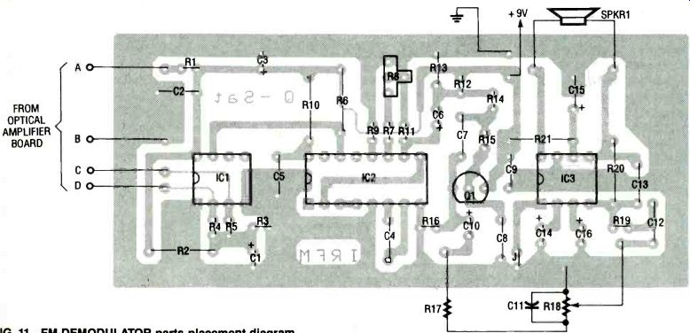
FIG. 11--FM DEMODULATOR parts-placement diagram.
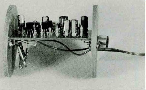
FIG. 12--HERE IS THE TRANSMITTER MODULE mounted on plastic disks that
fit inside the PVC pipe.
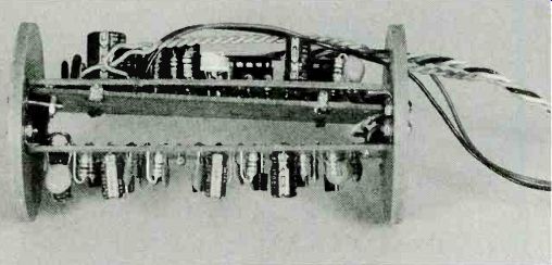
FIG. 13--THE OPTICAL AMPLIFIER and FM demodulator connect together with
the shielding board between them, and mount on plastic disks that
slide into the PVC pipe.
--------------
OPTICAL AMPLIFIER--PARTS LIST
All resistors are 1/4-watt, 5%. R1--100,000 ohms
R2--10,000 ohms
R3, R9, R10, R16, R2--315,000 ohms
R4, R5 150,000 ohms
R6, R17, R24-3300 ohms
R7, R12-100 ohms
R8--3900 ohms
R13, R14--5600 ohms
R11, R15, R18, R21--4700 ohms
R19, R22-22 ohms (see text)
R20-360 ohms
Capacitors
C1, C4, C8-10 µF, 16 volts, electrolytic C2, C5, C9 0.1 µF, ceramic C3, C12, C14-C16--0.01 µF, ceramic C6, C7, C11-470 pF, ceramic, 10% C10--0,001 µF, ceramic, 10% C13-100 µF, 16 volts, electrolytic
Semiconductors Q1MPS918 NPN transistor (Motorola)
Q2Q62N3904 NPN transistor (Q5 and Q6 must be a matched pair, see text)
D1-PIN diode (Siemens SFH205 940nm usable at 880nm, Panasonic PN323BPA 940 nm, Panasonic PN334PA 880 or 940 nm, see text)
Other components
SPKR1-8 to 45-ohm speaker
Miscellaneous: PC board, wire, solder, etc.
---------------
If you expect to transmit at distances over 1500 feet, the FM demodulator board must be shielded from the optical amplifier board. Some copper-foil covered single-sided PC board material can be used to make a shielded box, or a separate grounded metal box can be used. The prototype has a single-sided PC-board blank mounted on the bottom of the FM demodulator board with the copper side facing away from the underside of the PC board.
The shield, which is attached to the demodulator with desoldering-braid straps, also makes an excellent ground plane.
The Air Hop prototype was housed in 2-inch PVC pipe. Pipe couplers were used to mount the two-and-a-half-inch lenses.
If you need a three- or even four-inch system, PVC pipe of that diameter is available. The nice thing about PVC is that it's cheap, readily available from hardware and plumbing supply stores, and very strong. Figure 12 shows the transmitter board mounted on plastic disks that fit inside the PVC pipe. Although the demodulator could be mounted outside the pipe, the optical amplifier must be kept close to the detector. The leads from the detector to the amplifier should be less than 1 inch long. The transmitter's LED leads should also be kept short. Figure 13 shows the optical amplifier board and FM demodulator board connected together with the shielding board between them, all ready to slide into the PVC pipe. The optics are focused by sliding the transmitter and receiver modules in and out of the pipe, changing the distance between the modules and their lenses.
----------------------
FM TRANSMITTER
PARTS LIST
All resistors are 1/4-watt, 5 %.
R1, R5, R9, R15, R16--1000 ohms
R2--22,000 ohms
R3--10,000 ohms
R4-1000 ohms, potentiometer
R6-100 ohms
R7-5600 ohms
R8, R13--2200 ohms
R10--470 ohms
R11--50,000 ohms, potentiometer
R12--33,000 ohms
R14--15,000 ohms
R17, R18--22 ohms (see text)
Capacitors:
C1-C3, C6--1 µF, 16 volts, electrolytic
C4-100 µF, 16 volts, electrolytic
C5, C9--10 µF, 16 volts, electrolytic
C7--0.001 µF, ceramic
C8, C10, C11--0.01 uF, ceramic
Semiconductors:
IC1-NE555 timer
Q1042N3904 NPN transistor
LED1 LED4-1R LED (Optek 0P293A 880nm, Optek OP295A 880nm narrow beam, Lytron 940nm, see text)
Other components
MIC1 electret microphone
Miscellaneous: 4 "AA" batteries and holder, PC board, PVC pipe and plastic disks, hardware, wire, solder. etc.
OPTICAL AMPLIFIER--PARTS LIST
All resistors are 1/4-watt, 5 %.
R1--100,000 ohms
R2--10,000 ohms
R3, R9, R10, R16, R23--15,000 ohms
R4, P5--150,000 ohms
R6, R17, R24--3300 ohms
R7, R12--100 ohms
R8--3900 ohms
R13, R14--5600 ohms
R11, R15, R18, R21--4700 ohm
R19, R22--22 ohms (see text)
R20--360 ohms
Capacitors
C1, C4, C8-10 µF, 16 volts, electrolytic C2, C5, C9 0.1 µF, ceramic C3, C12, C14-C16-0.01 µF, ceramic C6, C7, C11-470 pF, ceramic, 10% C10--0,001 µF, ceramic, 10% C13--100 µF, 16 volts, electrolytic
Semiconductors:
Q1MPS918 NPN transistor (Motorola)
Q2Q62N3904 NPN transistor (Q5 and Q6 must be a matched pair, see text)
D1-PIN diode (Siemens SFH205 940nm usable at 880nm, Panasonic PN323BPA 940 nm, Panasonic PN334PA 880 or 940 nm, see text)
Other components:
SPKR1-8- to 45-ohm speaker
Miscellaneous: PC board, wire, solder, etc.
-----------------------
Optics and mechanics
During testing of the Air Hop, a 1-milliwatt transmitter was placed about twenty feet from the receiver and optical tests-such as measuring lens gain and finding focal distances-were performed. Remember that when you align the lenses, you can't see the infrared signal. There's nothing like focusing an image that you can't see! The only way you can tell if the signal is improving is by monitoring either TP1 or TP2; you should see a 50-kilohertz sinewave. The amplitude of the signal is proportional to the received signal strength. Expect tens to hundreds of millivolts.
The prototype worked well at power levels of 5 millivolts, peak-to-peak.
---------
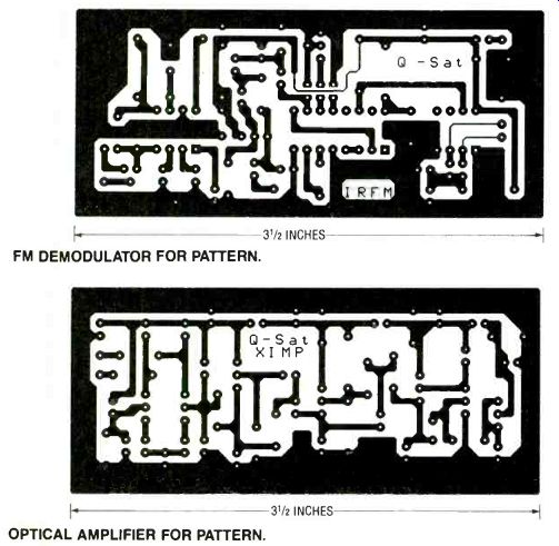
FM DEMODULATOR FOR PATTERN. INCHES
OPTICAL AMPLIFIER FOR PATTERN. INCHES
TRANSMITTER FOIL PATTERN.
-------------------
FM DEMODULATOR--PARTS LIST
All resistors are 1/4-watt, 5 %. R1-100 ohms
R2. R3, R6, R11, R13, R16 10,000 ohms
R4, R5--100,000 ohms
R7 33,000 ohms R8 50,000 ohms. potentiometer R9. R14, R1 568.000 ohms R17-4700 ohms R1 810,000 ohms, potentiometer R1 922,000 ohms R20 470,000 ohms R21-10 ohms
Capacitors
C1, C6, C10, C16-1 µF, 16 volts, electrolytic C2, C5, C9. C12-0.1 F, ceramic C3-100 µF, 16 volts, electrolytic C4, C7-0.001 µF, ceramic, 10% C8-470 pF, ceramic, 10% C11-0.01 µF, ceramic C13-100 pF, ceramic C14-4.7 F, 16 volts, electrolytic
C15-470 µF, 16 volts, electrolytic
Semiconductors
IC1-LM311 or LT1011 comparator
IC2CD4046 phase locked loop
IC3MC34119 audio amplifier (Motorola)
Q12N3904 NPN transistor
Miscellaneous: 9-volt battery and clip, PC board, blank PC-board material and solder-wick straps for shield (see text), PVC pipe, plastic disks, hardware, wire, solder, etc.
Note: The following items are available from Q-Sat, P.O. Box 110, Boalsburg, PA 16827: Complete Air Hop kit including all three PC boards (does not include speaker, 10K volume control, lenses, PVC pipe and batteries), AIRHOPKIT $30.00
Transmitter kit including one IR LED and PC board, AHTX-KIT- $11.00 Transmitter PC board only, AHTXPCB-$5.00
Optical amplifier kit including PIN diode and PC board, AHOPTAMPKIT$12.00 Optical amplifier PC board only, AHOPTAMPPCB-$6.00 FM demodulator kit including PC board (no speaker or 10K volume control), AHFMDEMODKIT-$12.00 FM demodulator PC board only, AHFMDEMODPCB-$6.00 Add $3.00 shipping and handling to all orders. Pennsylvania residents must add 6% sales tax. Please allow 3 to 4 weeks for delivery.
-------------------------
You can reduce the optical output of your transmitter for testing by using only one LED and by increasing the value of current limiting resistor R17 or R18 to a hundred ohms or more.
That is necessary because when you run the transmitter at full power from twenty feet, it will saturate the receiver. Saturation will produce a clipped waveform on either TP1 or TP2.
Because the system uses FM, the link will work fine, but it will be hard to tell if optical alignment is obtained when the signal is clipped.
Always try to get the best quality lens. Two dollars today will buy a piece of plastic that's bent into the shape of a lens-but it should do the job. The focal length of the lens can be found by focusing the sun to a small spot and measuring the distance between the lens and the spot.
Just to prove that you don't get something for nothing, there is a disadvantage in using lenses-beam width. The way the lens works on the transmitter is to gather the light from diverging source (an LED) and collimate it into a beam. The better the optics, the more collimated the beam. It's a little simpler with the receiver; the receiving lens simply gathers the light from a large area and focuses it on the detector.
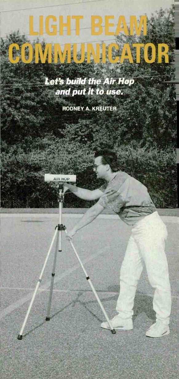
Trying to align the transmitter and receiver at a distance of a mile is quite a task, and good tripods are a must. The original Air Hop system had a rifle scope mounted on the transmitter to help locate the receiver. Two-meter handheld radios were also used for communication until the beams were aligned.
On the plus side, a tight beam is harder to "tap" than a phone line, if secure communications is what you want.
Using the Air Hop
There are two basic ways to use the Air Hop: with and without optics (lenses). If you wish to cover a broad area and short range, you'll get by without optics. Examples would be a set of wireless headphones, a remote control (such as for a TV), or a computer /printer interface. In those cases you can run as many transmit LED's as you choose. The basic system is set up to accommodate from one to four LED's. Four LED's with relatively large beam angles will flood a room with IR. If you want to achieve great distances, a system with optics is the only choice. Unfortunately, it's impossible to couple two or more LED's into a single lens. A lens has a small focal point, and one LED properly focused is the best you can get from a single lens.
Calculating distance
In central Pennsylvania where the author lives, it's hard to find a straight stretch of road longer than about a half mile.
(Roads are good for testing because the distance can be measured by using the odometer in your car or bike.) When the original Air Hop was tested in southwestern Virginia, short-distance ranges were set up along a road. Long-distance ranges were set up from mountaintop to mountaintop and measured with topographical maps.
There is a way to calculate how far your system will work without using a long optical path. The transmitter must be fitted with its collimating lens and adjusted for best performance because the lens-gain equations work only for the receiving optics. No lens should be used on the receiver for this test.
Set up your transmitter and receiver a reasonable distance apart-say 100 feet. Adjust the transmit optics for the best signal, and then move the receiver back until the signal gets a little noisy. (This experiment can occupy the best part of a day because the physical alignment must be performed each time you move the receiver.) If you obtain a distance of 250 feet, and were to add a three-inch lens with a gain of 24.5 to the receiver, the usable distance would be 6125 feet.
-------------------
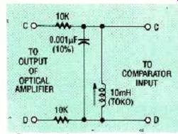
FIG. 14--THIS LC FILTER, placed between the output of the optical amplifier
and the FM demodulator, can increase the usable distance by decreasing
the bandwidth.
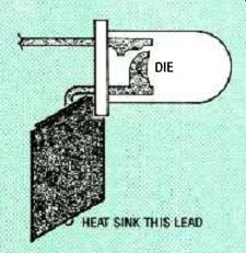
FIG. 15--AN LED'S EFFICIENCY falls with temperature. You can heat sink
an LED by soldering some heavy copper foil to the LED's cathode
lead upon which the die is mounted.

FIG. 16-YOU CAN REMOVE AN LED's lens by cutting off its end and polishing
the exposed surface.
------------------
Variations
The bandwidth can be increased by increasing the carrier frequency of the Air Hop. Of course, that would mean redesigning all of the filters in the system. A carrier of about 150 kilohertz should yield 15 kilohertz of audio bandwidth.
A simple LC filter placed between the output of the optical amplifier and the FM demodulator can increase the usable distance by decreasing the bandwidth. Such a filter is shown in Fig. 14. The series resistors control the overall filter width. An increase in resistance will cause a decrease in bandwidth. Values from 3.3K to 33K should work well. The filter should be tuned while the link is operating. Simply monitor either side of the LC tank with a scope, and tune for maximum voltage.
A parabolic mirror would be a better collimator for the LED than a lens. Consider a simple flashlight reflector or the kinds of flashlights with focusing lenses.
The efficiency of an LED falls with temperature, so keeping the LED cool will help. As a matter of fact, that's one of the major reasons why the author lost the original Air Hop competition. His opponent attached a heat sink to his LED by soldering some heavy copper foil to the LED's cathode lead, the lead on which the die is mounted. If you look closely inside an LED, you will see that one of the lead ends is larger than the other and is bent 90 degrees. That lead carries the heat out of the junction (see Fig. 15). It has been suggested that LED's with no internal lens are the best choice when coupling into an external lens. The lens top can easily be cut off a standard LED for experimentation as shown in Fig. 16.
Semiconductor lasers are now selling for less than thirty dollars in small quantities. One would probably vastly improve the Air Hop.
Most of the optical experiments were done with visible-light LED's, recognizing that the difference in using infrared LED's would be minor. For example, it was hard to collimate the infrared beam without being able to see it. By mounting four red LED's around the infrared LED, the collimation of the four red units was visible.
Because the IR LED was in the middle of the red units, it could also be aimed.
Even though the winning contestant had "cheated" by heatsinking an LED and running it at five times the rated current, the author would like to thank Gene Wood for challenging him to the original Air Hop contest-otherwise this project would not exist.
-R-E
Also see: HARDWARE HACKER