Learn about TV service from this step-by-step description of the repair of a faulty receiver.
BUSINESS STUDENTS LEARN Management techniques by studying business histories, and medical students learn to treat patients by studying medical case histories. Now you can learn how to repair a common problem in TV receivers by studying a service case history. The procedure is broken down into three steps: fault analysis, diagnosis, and repair.
The TV set discussed here is typical of many now in service around the world, and the fault is a common one and widely encountered, particularly after the set has been trouble-free for several years.
Case of the mute TV The "patient" was a Sylvania CX-1161W 19-inch color TV receiver. It was brought in for repair because the owner reported that after turning it on, there was no picture, no sound, and no raster. These symptoms immediately suggested trouble in the power supply. Figure 1 is a pictorial of the main circuit board that contains the components which were tested to determine the location of the fault in the circuit.
Two schematic diagrams, Figs. 2 and 3, are simplified copies of applicable sections of the manufacturer's schematics with the manufacturer's component designations included; they do not follow Electronics Now drawing standards.
The hand tools needed to perform this repair were those that are basic for all TV service, and include screwdrivers, needle-nose pliers, and a 40-watt soldering pencil. The test equipment used included a general-purpose oscilloscope, a digital multimeter with continuity checker, a plug-in isolation transformer, a variable transformer, and a laboratory, benchtop DC power supply with a built-in voltmeter and an ammeter.
The first step in the repair was the removal of the back cover from the set, giving access to the main circuit board. The principal components involved in this TV service case history are shown in Fig. 1, a drawing of part of the circuit board. Two fuses (FS500 and FS501) were mounted on the board. Figure 2 is a simplified schematic for the SCR-regulated power supply.
Because the power supply was suspected, the fuses were tested while the set was disconnected from the power line.
Fuse FS501 was found to be blown. Figure 3, a simplified schematic of the horizontal deflection circuit, shows that FS501 is in the B + line of that circuitry.
An ohmmeter check was made between the load side of fuse FS501 and ground and it showed a short circuit. The screws holding horizontal output transistor Q402 (in a TO-204 metal case) to the heat-sink were removed, and the transistor was removed from its socket. Another ohmmeter check showed a collector-to-emitter short. The ohmmeter also confirmed that with Q402 out of the circuit, the short between FS501 and ground was cleared.
This TV set had an SCR-regulated, low-voltage power supply with a full-wave bridge rectifier connected directly across the 120-volt AC power line. An isolation transformer (it has separate primary and secondary windings to isolate it from the power line) was inserted between the AC outlet and the line plug of the TV set to insulate the TV set from earth ground. This transformer reduces the risk of electrical shock from the "hot" chassis, and permits grounded electronic test equipment to be used for servicing.
In Fig. 2, it can be seen that the raw DC output of the bridge rectifier is regulated by SCR513, which, in turn, is triggered by horizontal-output sweep pulses modified by the pulse-width regulator (SCR-gating circuit). All other voltages, including those for the cathode-ray tube heater, are generated by windings on horizontal output transformer T402 shown in Fig. 3.
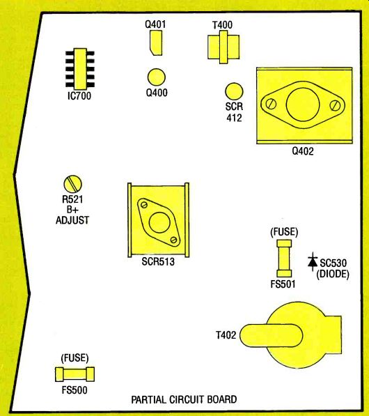
Fig. 1--LOCATION OF THE PRINCIPAL COMPONENTS on one end of a circuit
board discussed in this case study of a TV repair.
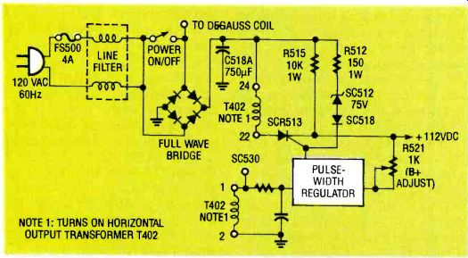
FIG 2--SCHEMATIC OF THE SCR-REGULATED receiver discussed in this case
history.
POWER SUPPLY for the color TV--NOTE 1: TURNS ON HORIZONTAL OUTPUT TRANSFORMER
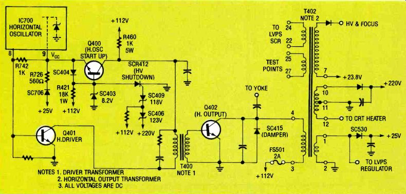
FIG 3--SCHEMATIC FOR THE HORIZONTAL DEFLECTION CIRCUIT of the color
TV receiver discussed in this case history.
When the TV set power switch S1 is turned on, approximately 158 volts of unregulated DC flows from the bridge rectifier through resistor R512, zener diode SC512, and diode SC518 to the gate of SCR513, dropping to a value of about 82 volts, which is sufficient to initiate TV set turn-on. (This 82-volt gate bias will not control SCR513 once it is on and +112 volts DC appears at its cathode.) SCR513 conducts for the required duration of the horizontal sweep interval during each raster line under the control of the pulse-width regulator (SCR-gating circuit) to maintain the + 112-volts DC output of SCR513. Notice that the winding between pins 22 and 24 of horizontal output transformer T402 is in series with the anode of SCR512. A negative spike from T402 turns off the SCR at the end of each conducting cycle interval in preparation for the next gate actuation. Also notice that the winding between points 1 and 2 of T402 is the source for the waveform that is controlled by the pulse-width regulator.
Immediately after the +112 volt line has been energized, current will flow through resistor R421 (see Fig. 3) to forward bias startup transistor Q400. Collector current flows through resistor R460. The resulting voltage ter is clamped to about 8.2 volts by diode SC404 and zener diode SC403. This voltage appears at pin 9 of the horizontal oscillator vertical countdown IC700, starting the oscillator.
Once the oscillator is started, rectifier SC530 rectifies the pulse voltage across pins 1 and 2 of T402 to develop + 25 volts.
That voltage is applied to diode SC706 and dropped by resistor R726 to appear at pin 9 as 8.6 volts at pin 9 of IC700 as 8.6 volts due to IC700's internal shunt zener regulator.
Horizontal deflection and, as a consequence the high voltage, can increase if a fault in the low-voltage regulator allows the voltage on the-volt line to increase beyond safe limits. It could result in a possible X-ray emission hazard. If this excessive voltage occurs, SCR412 turns on. With SCR412 conducting, the voltage at pin 9 of IC700 is grounded through diode SC404.
The gate of SCR412 senses the + 112-volt and + 220-volt lines. If either of these voltages is sufficient to cause the breakdown of zener diode SC409 (by sensing + 112 volts) or SC409 and SC406 (by sensing + 220 volts), SCR412 is turned on.
Repairing the TV
The proper operation of the horizontal deflection circuit was checked simply by substituting the proper voltage from an external power source.
It was then possible to determine if the proper drive was being applied to the base of the horizontal output transistor Q402.
To make that test, a + 25-volt supply was connected to the cathode of diode SC530 (the +25-volt source) and returned to chassis ground. Surprisingly, the 8.6-volt line at pin 9 of IC700 did not rise to its proper value. Was this due to a circuit fault or a sneak path? Schematic Fig. 3 shows that current can flow from the + 25volt source (cathode of diode SC530) through the series string of diode SC706, 560-ohm resistor R726, and diode SC404 to the base of Q400 and on through its collector (which is only reverse biased when + 112 volts is present). The path then goes through the primary of driver transformer T400 and on through the collector and emitter of horizontal driver Q401 to ground.
Transistor Q401 conducts under these static conditions because its base is forward biased by resistor R742. It is necessary, then, that Q400's collector be reverse biased. This was accomplished by applying about +40 volts to the +112-volt line. A convenient access point to the + 112-volt line was found at fuse FS501. (This voltage is high enough to perform the reverse-bias function, and low enough to minimize damage to other components if there are circuit faults). By applying both external voltages to the circuit and monitoring the base lead of horizontal output transistor Q402 with an oscilloscope, it was seen that horizontal drive was being generated. It shows up as a positive-going square wave that lasted about one half a line with an amplitude of approximately 0.7 volts (due to base-emitter clamp) and about 10 volts of negative spike at turn-off.
Transistor Q402 was replaced, and its collector was monitored with the oscilloscope. The waveform showed random pulses between the normal horizontal deflection pulses, as shown in Fig. 4-a. From experience, it can be expected that this symptom will be caused by one of the three following faults: Circuit loading due to shorted turns in the horizontal output transformer T402.
A bad yoke on the cathode-ray tube (CRT). Excessive loading on one of the voltages developed by transformer T402.
In applying the external 40volt test voltage, it was known that transistor Q402 would not be damaged because only 40 volts was being applied to the + 112-volt line. However, as expected, the temperature of Q402's case rose. After the CRT yoke was disconnected at its plug, the waveform did not improve. The plug was then reconnected to the yoke.
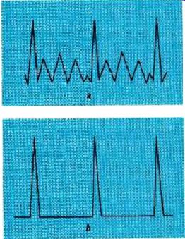
FIG. 4--OSCILLOSCOPE PATTERNS of spikes from horizontal output transistor
Q402: with defective output transformer (a), and with new transformer
(b)
Transformer T402 was then removed from the PC board and all of its wires were disconnected. Pins 3, 4, and 7 were reconnected with alligator-clip-terminated jumpers. With the application of the test voltages, the collector waveform of Q402 remained abnormal. The waveforms across the open windings were checked with an oscilloscope. The attempt to measure across pin 12 to pin 11 (ground) resulted in a half-inch spark discharge.
The spark discharge was an indication that transformer T402 had an internal short in its high-voltage winding. The short did not show up with a continuity check, indicating that the breakdown occurred only when voltage was applied to the transformer.
Transformer T402 was replaced, and all wiring connections were re-soldered. The 25- and 40-volt test voltages were applied as before. The oscilloscope waveform taken at the collector of Q402 showed a waveform with only "clean" vertical pulses, as shown in Fig. 4-b.
The external power supplies were removed and fuse FS501 was replaced. It was now clear that the faulty transformer was the cause of the problem. Power was applied through the isolation transformer in series with a variable transformer.
The oscilloscope was connected to test points 25 and 27 of T402, and the voltage was slowly increased while the oscilloscope pattern was observed. In addition, the +112 volt DC line was monitored with a digital voltmeter. When the voltage reached about 90 volts on that line, a picture appeared on the CRT screen.
The AC line voltage was increased further until the +112 volt DC line reached its nominal value. Further increases in the input AC voltage did not cause a corresponding increase in voltage on the +112-volt DC line.
This was an indication that the pulse-width regulator was functioning properly and not contributing to the problem.
The variable transformer was set to 120 volts on the AC line.
Then a digital voltmeter was set to its DC voltage scale, and its probes were placed between the + 112-volt line (FS501) and ground. Potentiometer R521 was adjusted until a reading of + 112 volts DC appeared on the meter. That measurement showed that B + was properly set. The TV set was then turned off and the test equipment was disconnected.
To verify that the TV set had been repaired, it was powered up again and allowed to run for several hours to see if any problems would occur. A visual and touch test was made on the operating TV set to confirm that there was no abnormal heating.
The vertical sweep controls were adjusted so that the picture filled the screen properly. This completed the repair. The TV set was then ready to be returned to the customer.
The repair would not have been successful if the three basic steps of successful TV servicing were not carried out. The first step, as obvious as it might seem, is to correctly identify the symptoms of the fault. Second is to study the circuitry to diagnose the cause of the problem.
Only then can the repair be undertaken with the hope of successfully completing the job.
Also see: Link |