by ALAN WINSTANLE
Welcome once again to Circuit Surgery, our regular clinic devoted to readers' problems. This month we describe a circuit for taking the "thump" out of audio systems. We also offer a Simple Fuse Tester. We begin with a "confusing" question....
Open all hours
I'm delighted to be behind the desk at Circuit Surgery, the monthly clinic to help resolve problems, pass on tips and share circuit suggestions. I'm sure readers have appreciated Mike Tooley's sterling work and I'll do my best to follow on by helping out with readers' queries and encouraging you to explore the truly fascinating world of micro electronics. Unfortunately space at "The Surgery" is strictly limited, however I will try to appeal to all sectors of our readership, from absolute beginners (such as many Teach-In '93 followers), upwards.
This is your column, so why not drop me a line with your ideas and queries for inclusion in Circuit Surgery? I'm also happy to pass on any readers' handy tips relating to constructional matters or circuit design. These will appear under the "Prescriptions" column from time to time--but I want your quick tips and ideas, so get writing! Meantime, stethoscope at the ready, here goes! Con-fusing Tom Baldwin of Romsey wrote in with a question on fuse ratings for low voltage power supplies: A recent 12V-0V-12V p.s.u. caused much confusion--I calculated peak power output on the d.c. side as 96 watts, and worked back to give a current rating on the mains side, to get a fuse rating. I made some allowance for capacitor charging but the mains fuse blew on power-up. I eventually used a fuse of what I thought was a dangerously high rating--where did I go wrong? Tom's circuit was a standard full-wave rectification and smoothing arrangement, driving a complementary pair of regulators with external pass transistors to boost the current output, giving ± 12V d.c. at some 4A. In general, the power dissipated in the primary (mains side) of a transformer is about equal to that in the secondary circuit (and power = voltage across the circuit x current through the circuit, remembering that these are r.m.s. values where a simple sinewave is involved), but you do need to allow for the high "inrush" which occurs on power-up, caused by the smoothing capacitor sucking in an initial charge.
Ignoring the load on the p.s.u., this surge is determined mostly by the resistance of the transformer windings and the size of the smoothing capacitor.
The actual value of electrolytics could be 50 to 100 percent higher than the marked value due to their poor tolerance, and this factor may also cause a higher switch on surge than expected.
You have to allow a margin for nuisance surges and for all low power mains projects with up to say 2,200µF or so of smoothing, I generally employ a maximum of 1A "quick blow" as a safe rule of thumb--500mA or less if possible--to give adequate protection in case of transformer or smoothing capacitor failure.
With heavier loads using larger smoothing capacitors (say 5,000p.F or more), it's probably best to use an "anti-surge" fuse instead--these have a coil spring built into the fuse wire which permits a high initial current to flow but will still rupture under sustained overloads.
It seems the most accurate way of deciding the fuse rating is actually to measure the average ac. mains current with a true r.m.s. meter then add a margin of say 50 to 75 percent, though for safety's sake I would not recommend that an inexperienced novice attempts a mains current reading at all. Such a meter automatically "corrects" the reading to compensate for the complex non sinusoidal waveform present in, say, a power supply, whereas a "normal" multimeter on an a.c. range is calibrated to produce an r.m.s. value based on an assumption that a simple sinewave is involved--adequate for most purposes.
Your P= IV calculation to obtain a current value is slightly misleading in this case because it inherently relates to a simple sinewave. In fact, the p.s.u. waveform is more complex and the average current is much higher in practice--hence the fuse kept melting! Some more "con-fusing" data--quality cartridge fuses are generally marked with a letter indicating their type: a type "F" is a quick-blow, "FF" is super-rapid (for semiconductor protection) whilst "T" is anti-surge or time-lag.
Incidentally, fuses can also "grow old" and it's not unusual for fuses to melt for no apparent reason--I repaired my color TV which suddenly stopped working when an internal fuse aged and finally failed altogether. A 5p. fuse saved me a $70 call-out bill!
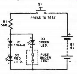
Fig. 1. Simple Fuse Checker circuit diagram.
Testing fuses
Still on the subject of fuses, Peter Strong of Tiverton asks: Should fuses be tested on the low or high resistance range of a multimeter? I would have thought the "low" range as a fuse is a low resistance device, but it seems that multimeters source more current on the low ranges which seems curious. Any explanation? When checking resistance with a multimeter, you're actually causing a "test" current to flow through the unknown resistance. The ohmmeter scale is calibrated as a function of the voltage across the resistor divided by this "test" current which is derived from the meter's internal batteries. (Actually, the test current flows out of the negative terminal of your multimeter!) A moving coil multimeter could source some 100mA or more on the lower resistance ranges, this current generally reduces to just a few mA on the highest setting. However a digital multimeter (DMM) will typically only source a matter of microamps on its resistance range.
So if you're testing a really low current fuse using a moving coil multi meter, it might be best to stick to a higher resistance range where there is less likelihood of melting the fuse! But if the fuse is rated at say 250mA or more, then it should make no difference which range you utilize as there is little danger of damaging an intact fuse this way and you'll easily see the difference between virtually zero ohms and infinite resistance.
Using the test probes of a multimeter to test fuses can be tricky, so the Simple Fuse Checker of Fig. 1 will help to test whether glass or ceramic fuses are intact or not. It's ideal if your vision is impaired and it is handy to have on the bench as a very simple GO-NO-GO checker. It can be built into a small plastic box using a push switch, with two metal pads being used as "contacts" on the surface, spaced to accommodate both 20mm and 1 1/4 inch types.
To use the checker, just bridge the pads with the suspect fuse. An intact fuse will enable the green l.e.d. 03 to light, the forward voltage of which shunts diode D1 and l.e.d. D2 which cannot illuminate. A faulty fuse (open circuit) will illuminate the red l.e.d. instead.
Use it to test household light bulbs too!
Speaker Anti-thump
C.L. Quay from Kuala Lumpur, Malaysia wrote in--thanks for the picturesque postcard!--with an idea which might appeal to audio fans: Building an amplifier is one thing, but to hear the "thumping" sound when you switch on is irritating. Can you help me with a simple "de-thump" circuit for my amplifier? The Loudspeaker De-thump circuit of Fig. 2 is broadly universal and could be fitted onto many domestic systems. Ad ding anything between the amplifier and the speaker system might give rise to unacceptable distortion so in this simple but effective design, a set of heavy-duty relay contacts is driven by a short-period timer. The relay switches in a dummy load immediately on power-up and connects the speaker system once the amplifier has had time to settle to its quiescent operating condition, by which time the thump should have passed.
Integrated circuit IC2 is a MOSFET op-amp connected as a regenerative comparator or Schmitt trigger, with a degree of positive feedback provided by resistor R3. This gives a crisp switching action with no relay "chatter". The inverting input of the opamp is connected to a simple RC network (VR1 and C3) which can be set for up to about four seconds delay. On applying power, the opamp output switches high and transistor TRI drives the power relay RLA. The normally-open contacts thus connect a power resistor (R6) across the amplifier out-put terminals, simultaneously disconnecting the speaker. Only when the RC net work has charged to more than 50 percent of the supply rail (set by R1 /R2) will the relay trip out and re-connect the speaker. This occurs after a short delay determined by the setting of VR1. There after, the circuit draws little current.
A protected transistor type LP395Z was used for TR1. It has thermal shutdown and current limiting (100mA) features so it's nearly impossible to destroy. The l.e.d. D1 is a bit of a gimmick and could be omitted: it lights for the timing period.
Fig. 2 shows the connections for one audio channel only, and the contacts RLA2 are used in a similar manner with another dummy load (not shown) for the other audio output.
It is probably best to power the circuit from the amplifier's existing d.c. supply which should manage the initial 100mA during timing (thereafter, hardly any current is consumed) and a typical 12V 100mA regulator (e.g. 78L12C) will withstand up to 35V d.c. absolute maximum input. Tap the supply from the main pcb as near as possible to the amplifier's power supply smoothing capacitors, so that the de-thump circuit will trigger as soon as possible on power-up. Alternatively, build a separate mains power supply to provide about 12V d.c. 100mA maximum, linking a mains transformer from the mains input of the amplifier.
------------------
COMPONENTS
De-Thump Circuit
Resistors
R1, R2 100k (2 off)
R3 1M
R4 4k7
R5 680 (optional)
R6 22 ohms 5W (see text)
All 0.25W carbon film ± 5%
Potentiometer
VR1 2M2 enclosed carbon preset
Capacitors
C1 0µ33 polyester
C2 0g1 polyester
C3 42 tantalum 16V
Semiconductors
IC1 78L12C 12V 100mA regulator
IC2 CA3140E MOSFET op-amp
TR1 LP395Z protected npn transistor
D1 red led. (optional)
D2 1N4148 diode
Miscellaneous:
RLA DPCO 10A relay 120 ohm (or greater) coil
Connecting wire; matrix or stripboard, solder etc.
Approx cost guidance only £8
----------------------
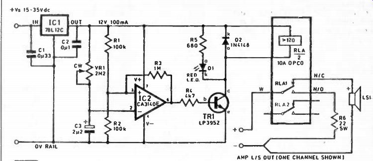
Fig. 2. Loudspeaker De-thump circuit diagram. The relay switches stereo
channels, of which the switching circuit for only one audio channel is shown.
The load resistor R6 is not critical in value or power rating. It is unlikely to dissipate power of any significant level during the brief timing period, hence a relatively low power rating--say 5W minimum--should be adequate. You may actually be able to omit the dummy load altogether--there were no problems running my Marantz "open circuit" and most modern units will be protected against open or short circuits. However, choose a high-rated relay such as one with at least 10A contacts. A drop of contact lube may also help counter noise.
An enhancement may be to reverse the two inputs to the op-amp and also exchange the n/o and n/c circuits on the relay. Then, the speaker is never connected during powering up and will only switch in after a delay. However the circuit will then consume nearly 100mA as long as the speaker is connected because of the relay consumption, so make sure you are happy the power supply can cope with this extra loading.
Next month: A further selection of reader's letters to encourage you to dabble. I also hope to cover one or two Teach-In topics as well. If you have any particular queries, please write to me c/o The Editor, 6 Church St., Wimborne, Dorset BH21 1JH and where possible I will try to reply through this column.
Regrettably I cannot guarantee an individual reply or advise on the repair or modification of specific commercial equipment. I'm afraid there simply isn't room to handle lengthy topics, but I read every letter and assess them for appeal and complexity. If you have any ideas or queries which you think might interest others, then write in! Why not send a postcard or photo, too?
(adapted from: Everyday Practical Electronics, Dec. 1993)