By Carl Babcoke, CET
Solid-state devices can be ruined easily by any large voltage transients that reach them. Inexpensive thyrectors are included in many late-model machines to hold the amplitude of line-voltage transients within the safety range. Several thyrectors are described, but most of the explanation is about metal-oxide varistors and how to test them.
Short-duration voltage transients ranging from 100V to 2000V often ride on the 120Vac line-voltage power that operates TV sets, radios, computers and many other machines. These transients are directly responsible for many unexpected failures in all kinds of electric and electronic products.
There is no single typical transient voltage or waveform. Nearby lightning strikes can produce pulses having thousands of volts across the ac wiring in homes. Other noise sources (such as a food mixer with a brush-type motor) might apply only a few volts of spikes that ride on the larger 60Hz sine waves.
Transients can have almost any form or amplitude. In general, lower-voltage transients occur more often, and higher voltage ones happen less frequently.
But a typical building might have thousands of over-400V transients per year. A transient monitor in farm home recorded about 300 pulses of 300V, one 20kV pulse, and hundreds of pulses between those extremes. Probably the 20kV transient was caused by lightning striking near the overhead power lines.
A chart showing transient voltages and frequency of occurrences averaged 2kV at 10 pulses per year, while the US composite curve had about 2000 400V transients at the low end and one 5kV pulse at the high-voltage end per year.
Transient voltages of these magnitudes certainly could be responsible for the many failures of solid-state components (especially diodes, transistors, SCRs and triacs) where no other defects or overloads can be found.
Because of these facts, plus the practical repair experiences of the industry, it is recommended that all electronic equipment should be protected against line transients up to 2kV. Protection to higher voltages (say to 5kV) probably is not justified because the extra expense of protection would be higher than the cost of the few failures pre vented.
Designers of industrial electronic equipment often specify diodes of twice the usual peak reverse-voltage ratings. This is one step in their efforts to stop repair expenses and production losses that occur because of damage from transient voltages on the ac lines.
-------------------
Origins of transients
Many line-voltage transients are generated by these sources: switching on or off of large inductive loads; commutating pulses in power-conversion units; voltage arcs; lightning strikes; and many other sources not under control of the equipment user.
In addition to transient pulses that arrive on the power lines, other destructive spikes can be produced by normal operation of electronic circuits, or by circuit defects. For example, if a power-supply transformer is switched on at the tip of a positive peak, a pulse and damped oscillation (of double the line voltage) can be gene rated at the transformer's secondary.
Pulses of higher amplitudes are possible when the same transformer is switched off at a peak of magnetizing current.
Amplitudes of 10 times the normal steady-state voltage have been measured.
A surge from the blowing of an overloaded B+ fuse can apply a huge pulse and ringing to all diode rectifiers in the same circuit. Probably the voltage pulse damages more diodes than the current overload does.
Repetitive arcs and transients from switch-contact bounce can add together, increasing the heat rise of components and multiplying the failures.
Many technicians have noticed diodes that are reverse-voltage connected from B+ to ground.
Perhaps some are zeners that regulate the voltage. But many others are installed to clip any negative-going transients (such as negative spikes or the negative peaks of ringing).
Transients that affect the life span of relays and solenoids will be discussed later In other articles.

---- Figure 1 Adding a capacitor across the ac line minimizes some
minor transients by forming an RCL-type of low-pass filter that integrates
the pulses. The resistance and Inductance sections of the filter are in the
power wiring.
Diode failures
When a high reverse-bias voltage is applied to a PN junction (in either a diode or transistor), an avalanche can take place at just one small point in the junction (because of field non-uniformity). And the resulting extreme heat ruins the junction, causing a short.
Because excessive internal heat is responsible for junction failures, the possibility of diode or transistor failure depends on these transient characteristics: total amplitude of the pulse; whether positive or negative polarity; steepness of wave-shape; duration; and the time between individual transients.
A pulse of long duration heats a transistor junction to a higher temperature than does another having the same amplitude but of shorter duration. One strong transient can destroy the operation of a transistor in just a few microseconds.
Transient voltages that rise or fall very rapidly can produce a kind of piling-up of voltage in sections of motor or power-transformer windings or other inductances. Turns of wire nearest the transient can arc or be overloaded while other turns farther away are not in danger.
Many line transients are narrow pulses with steep sides. Because line-voltage transients come in many unpredictable amplitudes, repetition rates and wave-shapes, it is difficult to find a single protection method that is effective against all transients. For example, a simple L/C filter that minimizes one type of transient might act as a tuned circuit to multiply the amplitude of another kind.
Blocking filters
Many low-amplitude transient pulses can be reduced below the danger point by routing the ac power through low-pass R/C or L/C filters. The most simple filter is a capacitor connected in parallel with the line-voltage wires where they enter the chassis. Resistance of the power wires plus the inductances of pole transformers furnish the top leg of the filter (Figure 1), while the added capacitor completes the filter.
Cascaded sections of L/C filters reduce transient amplitudes even more, but they must be damped highly to prevent ringing.
Clamping the amplitude
Another method of minimizing harmful transients is to short-out (or partially short-out) any portion of the waveform which exceeds a certain amplitude.
Crowbar: A crowbar protective device senses harmful overvoltage or overcurrent and places a dead short across both signal and transient. This resulting massive short trips the circuit breaker or blows the protective fuse. Of course, the circuitry cannot operate until the overload is corrected and the protective device is reset. It is a drastic remedy, but one that is justified with computers or digital equipment where a temporary cessation of operation is preferable to the wholesale destruction of ICs.
Clamping: Reduction of the higher amplitude portion of transients (by a resistance change that varies with the voltage) is called clamping. At the desired voltage, the clamping device draws little current (high resistance). A transient of about 120% or more of the steady-state voltage forces the clamp to draw a heavier current (low resistance) that reduces the transient by increased loading.
A spark gap is a simple type of shunt or clamp. Excessive voltage causes an arc across the gap, and the arc ionizes the air so considerable current can flow, thus reducing the voltage until the arc is extinguished. However, several microseconds must elapse before the current flow can become maximum, and the delay might allow the transient to reach a dangerous level before ionization occurs. Some follow-through current flows in the ionized path, often reducing the desired voltage or signal level.
Also, it is difficult to manufacture spark gaps having consistent breakover voltages, especially at lower voltages.
Neon bulbs are a specialized kind of spark gap, where neon (with its lower ionization point) replaces air.
Limitations are the small current flow before bulb damage occurs, and the lower quenching voltage compared to the ionization voltage.
An old-fashioned antenna lightning arrestor is an example of a spark gap. Many digital meters and picture-tube sockets have internal spark gaps to restrict maximum transient voltages.
One of the earliest true clamping products was made using reversed-bias selenium rectifiers. These are constructed similarly to selenium rectifiers, with the element deposited on large metal plates for better heat dissipation. Selenium transient suppressors did not clamp sharply, and had aging problems.
Zener diodes connected back-to back (opposite polarities) clamp very well, having negligible leakage at the desired steady-state voltage, but changing to strong loading (low resistance) for pulses of higher amplitudes. Zeners would be the best clamping device, except for thin junctions that place a low limit on the maximum current possible without excessive internal heating and damage.
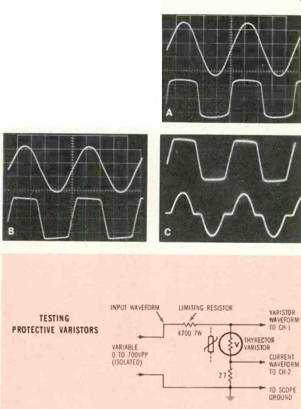
Figure 2
These waveforms show the voltage-clamping operation of metal-oxide varistors. (A) Top trace shows the 400VPP sine waves at the input of a 3300 ohm limiting resistor that was connected to a V33M A1 B varistor.
Across the varistor were 80VPP rounded square waves (lower trace). This includes both peaks, so transient clipping should begin at about 40V peak. About 200 M-o varistor leakage was measured by a VTVM, while a digital capacitance meter read 229 pF. (B) The sane measurements were made for a V130LA20A varistor.
Sharper corners were noticed on the 430VPP varistor waveform (this limiting resistor was 18 K-o). Leakage resistance was 90 M-o, and the capacitance tested 3,080pF (.0031pF). Notice the absence of any follow-through after currant. The end-of-conduction voltage is only slightly lower than the voltage that started the conduction. (C) Top trace is the varistor voltage, and bottom trace shows the current waveform. Notice that current flows only at the sine wave tips. (D) Most transient-type varistors can be tested for clamping voltage level and current waveform by connecting scope and varistor as shown. Input voltage should be about two to three times the clamping voltage. An alternate industrial symbol is shown for the varistor. Notice that most newer scopes are grounded through their power cable, so be certain the test voltage is isolated from raw 120V. A good source is a variable-voltage transformer (Variac or equivalent) feeding the primary of a tube-type power transformer, with the test voltage taken from the isolated step-up secondary of the power transformer.
TESTING PROTECTIVE VARISTORS
Varistors: The term varistor comes from the two words variable resistors. Until recently, the best varistor material for clamps was silicon carbide. The only limitation is the rounded knee of the curve (between conduction and non-conduction). If a silicon carbide varistor is designed for negligible leakage current at the desired working voltage, the resulting clamping voltage is too high to provide effective protection. If it is designed to give good protection by clamping transient voltages strongly, then it draws excessive power at the rated voltage.
A new family of transient-protection varistors is made of sintered metal oxides (usually zinc oxide with additives), and they provide a large change of resistance from nominal voltage changes (sharp knee on the conduction-versus-voltage curve).
These metal-oxide varistors can be manufactured in many different voltages and power ratings. The voltage rating is established by the varistor body thickness. The energy rating is determined by the total volume of material.
Current flows evenly through all areas of these varistors. There are no thin junctions or hot spots. This allows small varistors to have large dissipation ratings. Although similar in appearance to some ceramic capacitors, they are totally different inside. Instead of plates and dielectric elements, varistors have only one homogenous material in the body plus one connecting lead wire soldered to each flat side.
These varistors have capacitance which varies directly according to the area, and inversely with the thickness. Although the capacitance is usually no problem during the protection of power circuits, it is too high for some other circuits including RF stages.
Testing varistors
General Electric furnished three types of MOV-II varistors for examination in the Electronic Servicing Test Lab. During the testing procedures, several methods of determining the clamping voltage were developed.
If a metal-oxide varistor is checked for resistance with an ohmmeter, the reading of a normal component is in the high megohms, and there is no relationship between exact resistance and the clamping voltage or other characteristics.
Varistors have no polarity, so the ohmmeter readings are the same regardless how they are connected to a meter. They also work equally well on positive peaks of ac (or positive dc voltages) as on negative ac peaks (or negative dc voltages).
These facts must be kept in mind during all tests.
Of course, a shorted varistor is proof of a defect. When overloaded greatly, varistors sometimes explode. One operation at maxi mum rating sometimes ruins such a varistor, or many lesser conductions can cause failure after long periods of time. Therefore, if transient protection is vital, the varistors should be tested about once each year for clamping at the rated voltage.
Fortunately, a test for the approximate rating can be made easily.
Testing with ac and scope Figure 2 shows how to connect a variable-voltage ac source and a scope to measure the approximate clamping voltage (the voltage where slight voltage increases produce huge current increases).
The clamping voltage for dc is slightly different than it is for ac voltages; however, this is not important. A guard band between the working peak voltage and the clamping voltage always is provided, and a line-voltage increase of 10% does not increase the varistor current appreciably.
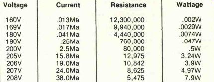
Table 1
Dc voltage was increased in steps through a 3300 ohm limiting resistor and a V130LA20A varistor, while the varistor voltage-drops and currents were measured with digital meters. As expected, the current increased rapidly when the varistor voltage approached the clamping level. The varistor became smoking hot at 208V, and the test was ended. (This varistor is rated at 50 joules for one large conduction, and is not intended for constant power dissipation.) Varistor resistances and wattages were calculated from voltages and currents. Varistor dc voltage and current
Measure in peak volts: Remember that all line voltages and clamping voltages must be expressed in peak voltages, which are identical to actual dc voltages and the dc-coupled scope calibrations.
In other words, assuming a sine waveform for the line voltage, the RMS value of each positive and negative peak must be multiplied by 1.414 to give the peak value. For 120V RMS, each peak measures 169.68V peak. Each peak is measured or calculated independently, because these varistors respond to each peak separately.
Figure 2B shows a peak-to-peak voltage of 430V for the clamped (clipped) lower trace. (Both peaks are shown, so peak-to-peak is the correct term.) However, this actually is the clamping of each peak at 215V peak. The guard band then is 215V minus 169V wide. No appreciable clamping occurs until the waveforms or transient spikes ex tend 46V or higher above the normal line voltage sine waves. One single-peak voltage at 135V RMS is 190.9V peak. Therefore, line voltages up to 135V RMS can be accommodated before the peak voltages come uncomfortably near the 215V limit.
Similar calculations are required for other steady-state voltages. Of course, the manufacturers always list the recommended RMS sine-wave voltage in the varistor specifications.
DC clipping
One of the GE number V130LA20A MOV-II varistors was tested with manually varied dc voltages, and the results are listed in Table 1. The measurements were stopped at 208V dc because the steady-state wattage became excessive there. In fact, the varistor smoked and the coating became soft from the 8W of continuous power. These varistors are rated for transient operation. not steady-state conditions, so the scope method is recommended for practical tests in the field. The table does illustrate the rapid change of current for small changes of voltage at the rated clamping point.
Zener versus varistor clamping A comparison between diode and varistor clipping is shown in the Figure 3 waveforms. Previous tests have shown diode and zener clip ping to be similar, except for the voltage differential. Therefore, the waveform clipping should be typical of zeners also. Tops and bottoms of the varistor waveform are not flat with sharp corners as are those with a zener. Therefore, the varistors have a broader knee in the curve, but one that is satisfactory for the application.
Capacitance effects
Figure 4 illustrates an extreme case of phase shift and amplitude reduction from the large internal capacitance of a varistor. Phase of the 60Hz signal was delayed about 1/8 cycle. A V130LA20A GE varistor was supplied with 60Hz voltage through a 1M resistor. With about 440V input to the resistor, the varistor voltage was about 210V. Part of the drop was from the varistor resistance (about 1.2M at that low voltage), while more loss came from the varistor's 0.003pF capacitance. The same capacitance was responsible for the lagging phase.
Smaller varistors have lower capacitance, but all have much more than normal resistors. Although the capacitance prevents these varistors from being used at RF, for example, it usually is an advantage when used in transient-clamping operation.

Figure 5 Clamping ability of the 130V RMS varistor was tested by adding large
pulses to the line voltage. Top trace shows the 330VPP sine waves with a 680VPP
positive pulse on each positive peak and a 680VPP negative pulse on each negative
peak. After the varistor was connected, the pulses were clipped very well
(lower trace).

Figure 3 These waveforms illustrate two differences between varistors (top
trace) and diodes (bottom trace).
Varistor conduction is more gradual.
Notice the rounded corners and slightly bulging peaks in the upper trace, compared to the sharp corners and flat clipping of the diode (lower trace).
Secondly, a diode clips (conducts) at zero volts (actually, 0.7V on either side), so it removes one entire peak without changing the other (lower trace). By comparison, a varistor clips at a certain substantial voltage on both positive and negative sides of zero voltage. For example, one varistor type clips at +215V on the positive peak and at-215V on the negative peak (parts of both peaks are removed by clipping, as shown by the upper trace). Diodes have polarity; varistors do not have polarity.

Figure 4 The large .0031pF capacitance of the 130V varistor gave a substantial
phase delay when connected in series with a 1M resistor. Top trace shows the
input waveform of 440VPP, and the 210VPP delayed voltage across the varistor
is shown by the lower trace. This is a dual-trace simultaneous picture, so
the phase is correct.
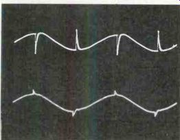
Figure 6 Pulses were not clipped unless they extended far enough beyond the
sine wave. Top trace shows varistor clamping of sine waves having out-of-phase
pulses. Although the pulse tips above the clamping level were removed, the
total pulse amplitude was not reduced very much.
When the same pulses were changed to in-phase (positive pulses to positive peaks and negative pulses to negative peaks, more of the amplitude was eliminated, as shown by the lower trace. There is a possibility that such incompletely clipped out-of-phase pulses might damage semiconductors.
Perhaps filtering is needed In addition to clamping.
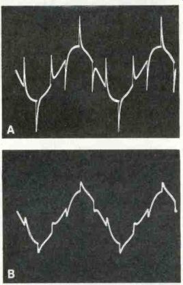
Figure 7 Third-harmonic pulses of 180Hz repetition rate were added to 60Hz
sine waves to permit testing the effectiveness of removing the pulses by capacitative
filtering. (A) This is the pulse/sine waveform without the added capacitor.
(B) Connecting the 0.047pF capacitor across the line reduced the pulse heights
very well.
Notice that the pulses along the sine wave's slopes were reduced as much as those at the tips. Also, the pulses were widened (longer duration) as the filtering reduced the amplitude. This is the way pulse and spike Integration operates. Total power of the pulses Is the same before integration as after integration. Pulses are not "absorbed" as is stated sometimes.
Operation with test transients
To verify the clipping of transients by metal-oxide varistors, a source of high-amplitude 60Hz pulses was connected to an isolated sample of 60Hz line voltage. Then waveforms were made both with and without the varistor, as shown in Figure 5. The individual positive and negative pulses of 680V peak were clipped just above the 330VPP sine wave, proving effective clamping at the correct voltage. However, the question arose about clipping pulses that were not extending beyond the peaks. Figure 6 shows positive pulses on the negative peaks and negative pulses on the positive peaks.
As expected, the out-of-phase pulses were not clipped unless the total pulse-plus-sine amplitude exceeded the clamping point. This might compromise the protection if these pulses then travel in the equipment beyond the point where the 60Hz waveform is removed.
Power transformers do not necessarily pass pulses according to the turns ratio. It is possible for the secondary to have equal or greater pulse amplitude than is present at the primary.
For these reasons, the use of both varistor and capacitance transient removal is recommended.
Capacitance filtering
In these simulated tests, both the varistor and the 0.47pF capacitor (Figure 7) reduced the pulse amplitude about the same. However, with real power systems having much lower impedances, the capacitor would reduce only the narrow high-repetition spikes. And a capacitor has very limited storage power.
In actual practice, a varistor no doubt gives better protection than a capacitor alone does. But remember that many new TV receivers have both a transient-protection varistor and a bypass capacitor.
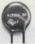
Figure 8
This picture shows the type of metal-oxide varistor used most often for 120V operation in TV sets and industrial controls. When tested for resistance by VOMs and most digital multimeters, a good varistor should read above the highest range.
However, a VTVM will show a capacitative kick and perhaps a 100M-ohm reading. But the best test is to measure the clamping voltage using ac voltage and a scope, as described before. Remember that a varistor minimizes transients by operating as an open circuit to amplitudes below the clamping voltage, or as a very low resistance to amplitudes above the clamping voltage.
Waveforms with the capacitor and without it are shown in Figure 7.
Summary
Any component resembling the one in Figure 8 that is in the power wiring, without any obvious function, probably is a transient-clamping varistor.
These varistors seldom fail in normal operation, except in localities where frequent strong transients are found. One or more huge transients or many smaller ones can ruin a varistor.
Therefore, all varistors should be tested periodically. The first and easiest test is to measure the resistance (while the varistor is disconnected from the circuit), preferably with a VTVM or FET analog meter having a high range with 10M in the center and a maximum of about 1000M. A shorted varistor obviously is defective. If the meter pointer gives a charging swing (as though testing a 0.01pF capacitor) and then slowly rises to above 100M, the varistor probably is normal.
A lead wire could come loose, or be burned loose by a huge transient. This type of open circuit should be found during the resistance tests. A varistor that has absorbed a large number of transients might become only partially effective, or might clamp at an excessive voltage which would not protect completely.
Protective varistors should not change in capacitance very much unless they become defective. Therefore, the capacitance should be tested when a varistor is installed. Capacitance tests made later then serve as an indication of detrimental changes. At the factory, new varistors are capacitance tested by an ac bridge having a 1MHz frequency. When tested by a digital-readout meter (such as the B&K-Precision used during these tests), the reading probably will be higher.
The most accurate field test for proper clamping is to apply sufficient 60Hz voltage through a limiting resistor to the varistor and measure the peak voltage between the clipped tops and bottoms, as shown in Figure 2.
Also see: Practical transient protection
Locating AC leakage in industrial plants