By Sam Wilson
Microprocessor
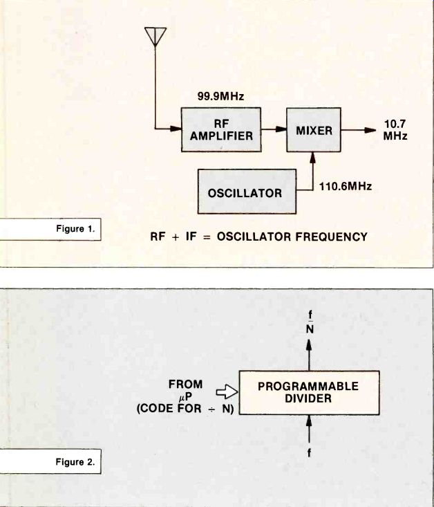
Figure 1.
Figure 2.
The title of this article is a misnomer because in the tuning system described here, the microprocessor performs a relatively minor task. The important work is done by a phase-locked loop.
The weakest link in a broadcast system seems to be at the point where the listener selects the desired station. Many different types of tuning have been tried.
None of them are totally successful.
With the analog system the listener turns a knob that moves a pointer across a numbered dial.
When the desired station is reached, the listener stops tuning.
Unfortunately, the dial often overshoots the mark and the result is distorted sound.
The microprocessor tuner is designed to eliminate the possibility of a mistuned station. It is a great innovation for people who really do want to listen to music.
The block diagram in Figure 1 is for a typical tuner in a superheterodyne receiver. If this is an FM tuner, it must be able to select one of 99 channels or stations between 88.1MHz and 107.9MHz.
With 99 stations available, it is possible to make a detent tuner that stops at each of the 99 carrier frequencies. In that case, the de--tent tuner would do the same job as the microprocessor tuner does.
For this discussion, we will assume that the listener has selected a station at 99.9 MHz. As shown in Figure 1, the local oscillator must be tuned to 110.6 MHz in order to get a difference frequency, or intermediate (IF) frequency, of 10.7 MHz.
Note the equation: radio frequency + intermediate frequency = oscillator frequency
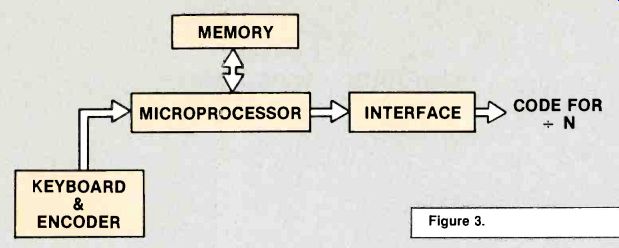
Figure 3.
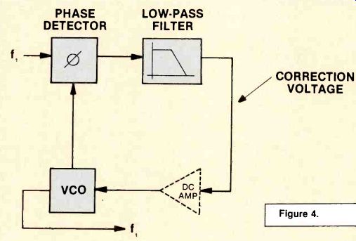
Figure 4.
You will need this equation to understand the following material.
I am going to start by discussing the various parts of the tuner.
Figure 2 shows a programmable divider. Its purpose is to divide any frequency (f) by a whole number (N). The divisor is selected by a binary code that is delivered to the programmable divider from the microprocessor. In this system, there are 99 different channels, so there must be 99 different codes for selecting any of the available FM channels.
Figure 3 shows the keyboard and microprocessor system that is used for selecting the desired code to be delivered to the programmable divider.
If you have read any of my material on microprocessors, you know that I insist that it is nothing more than a device that implements memory. As a matter of fact, that was the original reason for redesigning the microprocessor. The memories were becoming so complicated that the electronic circuitry needed for implementing them was getting out of hand. The microprocessor makes it possible to utilize the memory with a minimum amount of associated circuitry.
The various binary codes for setting the programmable divider are stored in the memory.
The keyboard and encoder make it possible for the consumer to select the desired station. Any keyboard number less than 88.1 or over 107.9 will be rejected by the microprocessor. The encoder converts the numbered keyswitch into a binary code that can be used by the microprocessor. That binary code tells the microprocessor to get a certain number out of memory and deliver it to the programmable divider.
The keyboard is the weak link in this tuning system. In fact, the complexity of the keyboard may be well beyond the comprehension of the average listener.
Figure 4 shows a typical phase--locked loop. The input frequency (f,) comes from a stable oscillator source. The first block in the loop is marked with the Greek letter 0, which stands for phase comparator.
------- Figure 5.
The output of the voltage-controlled oscillator (VCO) and the reference frequency (f,) are compared in the phase comparator.
The output of the phase comparator is a dc voltage with a magnitude that depends upon the amount of phase difference between f, and the VCO signal. If there is no difference between these two frequencies, the output of the phase comparator will be OV and no correction will be made. If, however, there is a phase (or frequency) difference between f, and the VCO signal, a do output voltage will appear at the output of the phase comparator. That voltage is used for correcting the VCO frequency.
The next block in the loop is a low-pass filter. The symbol shows a typical low-pass filter characteristic curve. This filter prevents f, and the VCO frequency from being passed around the loop.
The next step in the loop is a do amplifier. It is drawn with a broken line because not all phase--locked loops have this amplifier.
Its obvious purpose is to increase the range of the do correction voltage before it is delivered to the VCO. When the VCO frequency is identical to the incoming reference frequency, there is no correction from the do amplifier (or, from the low-pass filter) and the VCO output is equal to f,. Not much has been accomplished because the output frequency is the same as the input frequency.
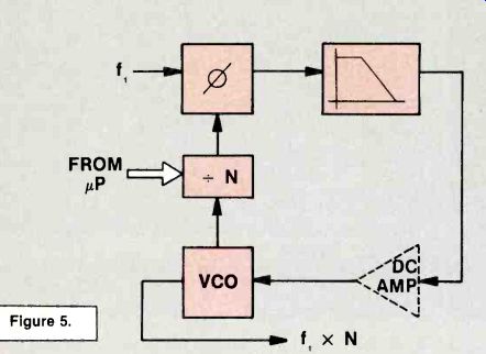
In Figure 5, a programmable divider (= N) has been added to the loop. Remember that the input to the phase detector must be two frequencies that are identical. Suppose that--N is set to divide by 2.
(This is not a practical number in the real tuner, but we are using it for an example to show how the VCO is affected.) If you divide the VCO frequency by 2, then it is obvious that the VCO frequency must be exactly twice f,. Then, when it is divided by 2, it will be exactly equal to f,. Therefore, the VCO output would be 2 times f, in that simple example.
Regardless of what value of N the microprocessor sets the programmable divider for, the output frequency from the VCO will be N times the input frequency.
The reference input (f,) may come from a crystal-controlled oscillator. So, by using the phase--locked loop with a programmable divider, the crystal oscillator frequency can be multiplied by any number set by the microprocessor.
The important feature of the circuit is that the VCO output is highly frequency-stable because of the crystal input at f,. In other words, you can have a wide variety of crystal-controlled output frequencies with this simple circuit.
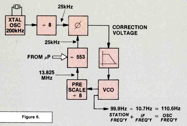
Figure 6 shows the phase-locked loop for producing the crystal-stabilized local oscillator frequency of 110.6MHz as shown in Figure 1. A 200kHz crystal oscillator is used for stability in the circuit of Figure 6. That crystal oscillator frequency is divided by 8 to produce a 25kHz input to the phase detector.
For the phase-lock to be stabilized, it is necessary that the input from VCO also be 25kHz. To obtain that, the programmable counter divides the VCO by 553 and the pre-scale _ 8 circuit divides the VCO output by 8.
If you have your calculator handy, you will see that the VCO must be operating at 110.6 so that when it is divided by 8 and then by 553, the result will be 25kHz. That will match the 25kHz from the crystal circuit and a phase lock will be obtained. If the VCO should try to drift off frequency, the output from the phase comparator will send a correction voltage through the low-pass filter and bring the VCO back to the proper frequency.
Note: There is no do amplifier in the phase-locked loop of Figure 6.
If the listener tunes to another station, the input from the microprocessor always will set the programmable divider so that it divides by the proper amount in order to get a phase lock. The output of the VCO then will be the proper frequency for the tuned station.
---- Figure 6.
Dichotomy
Reader Terry Bohning has proposed a different and interesting answer to Question No. 6 of the quiz in the August 1986 issue.
Here is the question and the answer given:
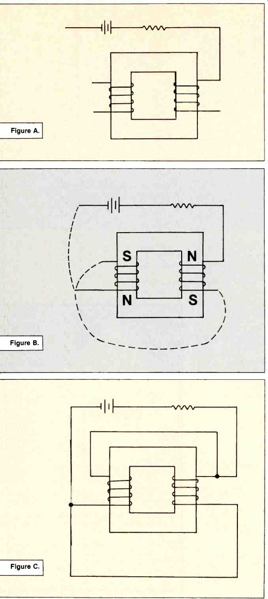
6. Connect the coils and battery circuit in Figure A to obtain maximum flux in the iron core. The solution given in the August issue is shown in Figure B. Terry Bohning writes: "Given some of the trickery in past quizzes, I was a little surprised not to see the following answer to Question No. 6 in the August 1986 quiz (see Figure C). This produces a slightly greater current in the coils, hence flux density." This is not the first time there has been a practical answer proposed to a theory question.
As I see it
There is no resistance value shown on the coils in Figure A, so it must be assumed the resistance is zero. As far as circuit current is concerned, it doesn't matter whether you connect them in series or parallel.
Also, "maximum flux" means (to me) that the core is saturated.
There can only be two possibilities: coil fluxes aiding (for saturation), or coil fluxes opposing (for zero flux). As Terry Bohning sees it From a practical standpoint, coils have some resistance whether stated or not. Connecting the coils in parallel will produce an increase in current and a resulting increase in flux. (He does not read saturation into the expression maximum flux as stated in the problem.) Summary If the parallel connection does, in fact, cause a greater flux than the series connection, then it must be assumed that the coil resistance is an appreciable part of the circuit resistance. This assumption is not supported by any information given in the problem.
If the question was worded in such a way that you had to make assumptions about coil resistance in order to get the answer, it would really be a trick question! It doesn't matter whether you think of flux as being saturation or just a large amount, the series or parallel connection does not affect the answer. It really is a matter of whether you want the flux to go to zero if a coil opens (series), or, whether you want some flux to be present when a coil opens (parallel). Terry Bohning has given an interesting and different way of looking at a question. I feel that his answer is as good--but not better than the one given in the August issue.
(Trickery? I'm crushed.)
---- Figure A. Figure B. Figure C.
Also see: Link | --Scoping TV power supply sources