By Sam Wilson, CET---Wilson Is the ES&T electronics theory consultant.
In the last issue we borrowed the space ship from "Fantastic Voyage" and took a trip into a small block of germanium. Stopping just inside the surface, we ob served Brownian motion and intrinsic current. We will now make a return trip to observe some new sights.
Our lab assistants are told to place a very small opaque dot behind us after our space ship enters the block of germanium.
Special lab equipment is needed because we have been reduced to a size that is invisible to the human eye.
Just inside the surface we stop and wait. When the black dot is in place we signal the lab assistants to shine a very bright light on the surface. The light penetrates the surface and bathes the atom in an eerie glow.
Huge objects that look like boulders come crashing into the material from behind. They are photons- that is, particles of light.
We are protected from these photons because they cannot pass through the black dot that was placed behind us. The high-speed boulders crash into the atoms of germanium and knock electrons loose. This greatly increases the intrinsic current that we noted in our previous journey.
At our signal the bright light is turned off and we move into the crystalline structure. It is necessary to provide our own light for this part of the journey.
We are still fascinated by the beautiful and orderly structure of atoms. Our space ship pulls along side a place where a larger atom has been wedged into the crystal.
It obviously does not belong there because it does not fit into the lattice structure.
This out-of-place atom is thrashing about, but it is firmly stuck.
We are told by the guide that it is called an interstitial atom. It is, in fact, an atom of copper that has somehow become trapped between the atoms of germanium.
A passenger asks why electrons are landing on and taking off from this atom. We are told that the copper atom is a form of deathnium trap. It captures electrons momentarily, disrupting the flow of charge carriers through the material. If there are too many deathnium traps, the material is worthless for use in diodes and transistors.
We are reminded that the things we see on the trip through germanium are identical to what we would have seen if we had entered silicon.
At out next stop we observe in the lattice structure an atom that is slightly larger than the other atoms. An electron is circling it like a tiny moon. This is a donor atom used to make the block of germanium N-type. If an external voltage is applied, the circling electron can easily be pulled away from its atom.
While the circling electron is loosely attached to its atom, there is no unbalanced charge. It belongs there and it is both electrically and gravitationally attracted to its atom.
So, the N-type material is not negatively charged. (Nor is the P-type material positively charged.) A better name could have been chosen for these materials so as to avoid the mis taken idea that they are negatively or positively charged.
Our ship makes a wide 180° turn so we can emerge from the same side as we entered. However, our path is soon blocked by what appears to be a wall. All of the atoms along the surface of this wall have fallen out of place so that the lattice structure is no longer intact.
It is another kind of deathnium trap. This one is called a grain boundary. We are told that this deathnium trap will make the germanium useless for semiconductor work.
You can see one or more grain boundaries in an ice cube. They look like an internal crack. However, if you turn the ice cube and try to look at the grain boundary on edge it will disappear.
We contact the lab assistants for help. Their computer plots a path around the grain boundary and we leave the surface of the cube. As we are being returned to full size we are told that we would surely have been stuck if we had tried to pass through the grain boundary. I decide against any future trips. I'm no hero.

FIGURE 1

FIGURE 2
FIGURE 3
The programmable Shockley diode
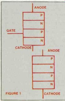
In a recent issue I noted the similarity between the model used for a Shockley diode and the one used for a 4-layer (Shockley) diode.
(See Figure 1.) I had heard from some source- which I can't remember-that an SCR can be used as a Shockley diode if the gate is left open.
Two students at New England Institute of Technology in West Palm Beach, FL, decided to try it and got some astonishing results.
When Randall Wolf and Glen Langley tried to make an SCR into a 4-layer diode, they found they didn't have enough voltage to make the device break over in the forward direction. So they decided to lower the forward breakover voltage by applying a slightly positive potential to the SCR gate.
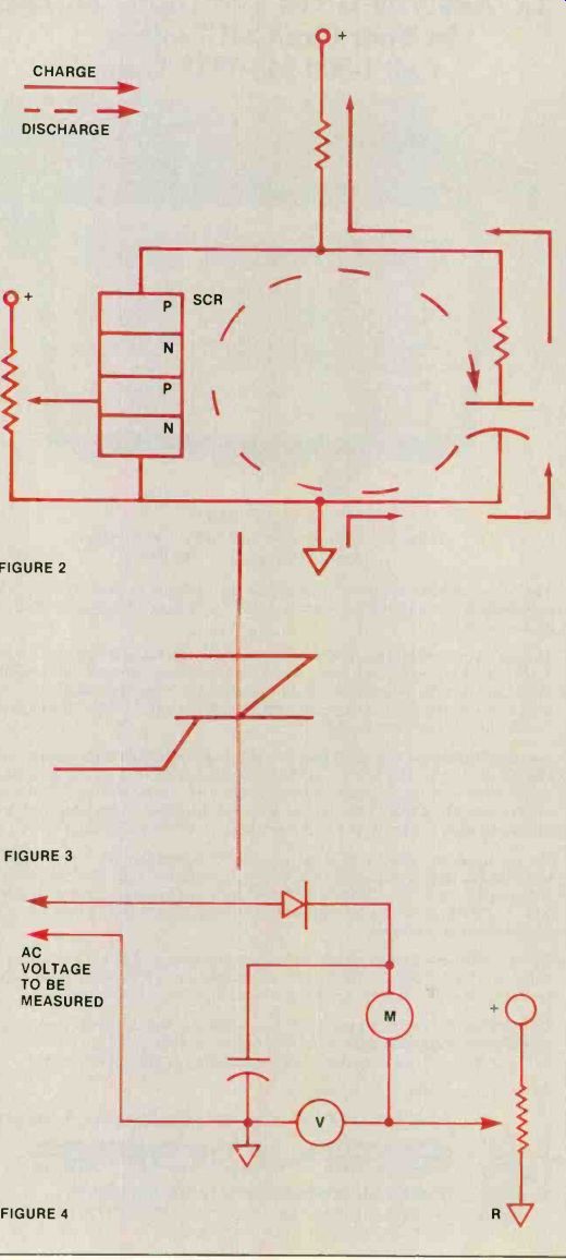
Figure 2 shows the circuit they used. Their reasoning was that if the device did break over, it should produce oscillations. The arrows on the schematic show the charge and discharge path for the resulting relaxation oscillator.
The device did break over and oscillation occurred. More important, the frequency could be changed. Therefore, changing the gate voltage changes the forward breakover voltage. That makes it a programmable 4-layer diode.
The students have applied for a patent disclosure letter. Figure 3 shows their suggested symbol.
I, for one, never cease to be amazed at the innovative ability of students! The slide-back meter I had a chance to talk with my friend Earl Tickler at the recent NESDA/ISCET/TESDA convention in Memphis, TN. His students at RETS (in Baltimore) requested that I discuss the slide-back voltmeter in my article. It was mentioned in a previous "Test Your Electronics Knowledge." The slide-back meter is used primarily to measure the peak voltage of a sine wave. The basic circuit is shown in Figure 4.
When there is no ac voltage applied, the sensitive meter reads zero current. Actually, a very small amount of leakage current may flow, especially if the probes are not isolated from each other.
When the ac voltage (to be measured) is applied, it is 1/2-wave rectified by the diode. The arm of R is adjusted until the current meter reads just a hair above zero.
In other words, the cathode of the diode is made positive enough that it will not conduct. The reason you want a very slight indication on the current meter is to make sure you are just at the peak point of the ac voltage input.
At that point the voltmeter indicates the peak value of the unknown voltage.
The question asked by others listening to our conversation was:
"Why bother? You can do the same job with any modern oscilloscope." There were several replies that are worth considering.
You wouldn't know whether you liked the idea if you didn't know what it was.
It is cheap. Some young experimenters haven't obtained an oscilloscope yet, so this gives them a way to measure the peak voltage.
It is important to periodically re view some of these older techniques. There may be an application in modern technology.
Stick-on meter No, this isn't another meter circuit. Don Turner, CET, of West Palm Beach, FL, sent this tip.
When making measurements in the field, he got tired of trying to find a place to put his VOM, so he attached a suction cup to the back of the meter. He used epoxy, but he said that a small screw could also be used.
Whenever he makes measurements, he just sticks the meter on to a nearly flat, smooth surface.
If any other reader has a favorite technique, please send it along.
A letter from Raymond McCoy
Dear Sam:
At the end of your "What Do You Know About Electronics," page 46 of the May 1987 issue, you quoted a college professor as stating, "A battery cannot produce voltage at any time unless current is being drawn from that battery." In my opinion, a battery is always drawing current. A better way to phrase the statement is:
"A battery is always producing voltage because current is always being drawn due to its discharge current (no matter how minute).
This discharge current is created because NO insulator is perfect." Thanks for the letter, Raymond McCoy. I found your comments on the battery interesting. According to your idea of the imperfect insulator, it could very well be impossible to prove that current is not required for producing a battery voltage.
Also see: Computer-aided circuit design
Troubleshooting the chopper circuit