By Victor Meeldijk [Victor Meeldijk is Reliability and Maintainability Engineering manager, Diagnostic Retrieval Systems, Oakland, NJ.]
One obvious reason that components fail is that they just wear out. But there are man' other causes, including inadequate design, careless handling and disregard of manufacturer recommendations, that you should take into account during troubleshooting.
Troubleshooting and subsequent failure analysis of system malfunctions often identifies the problem as an individual component failure. Besides random failures and manufacturing defects, the failure may have been caused by an incorrect application (by either system or component manufacturer), improper device handling (besides those caused by electrostatic discharge damage) or failure to follow manufacturer-usage recommendations. Some actual case histories follow.
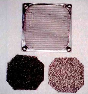
Figure 2. These fan filters are typical of those being used.
FOAM FILTERS ROOM WITHOUT FILTER
NOTE: The more pores per inch, the greater the pressure drop. Density of material is not related to pore size.
TABLE 1. Temperature measurements (in °F) or a unit showing the differences in effect with and without far filters. and according to PPI.
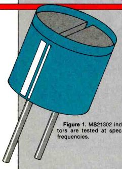
Figure 1. MS21302 inductors are tested at specific frequencies.
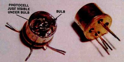
Figure 3. TF is optoisolator has an incandescent bulb design.
Application problems
Inductors per military specification MS21402 are specified and tested at specific frequencies. One device, for example, has an inductance range from 900 uH to 1,1001.4H at 0.790MHz. At frequencies of between 48kHz and 96kHz, it was discovered the range varied from a low of 955tH to a high of 1,1481H at 48kHz to a range of 94141 to 1,164k.H at 9kHz. The inductance range, therefore, shifted upwards at the lower frequency usage range.
Fan Filters
Fan filters usually are taken for granted and specified at the end of a design project, without thought to the serious problems that may arise. Figure 2 shows typical fan filters, both metal and foam type.
Depending on the pores per inch (PPI) of the material used, fan filters can cause a significant difference in ambient temperature vs. internal equipment an--temperature. Some typical measurements taker, on a piece: electronic equipment are shown in Table 1. Clearly, the porosity (and thickness of the filter material selected) influences equipment internal temperature rises.
Optoisolators
Random vibration, per Navy material specification (NAVMAT) P-9492, may be specified on Navy procurement contracts. This specification calls for random vibration at specified levels.
Circuit cards tested to these vibratory levels experienced optoisolator failures. Failure analysis of the parts revealed that the design used an incandescent bulb and photocell (Figure 3) with the bulb filament opening due to the vibratory exposures. A replacement solid-state optoisolator, using a LED, was recommended by the device manufacturer.
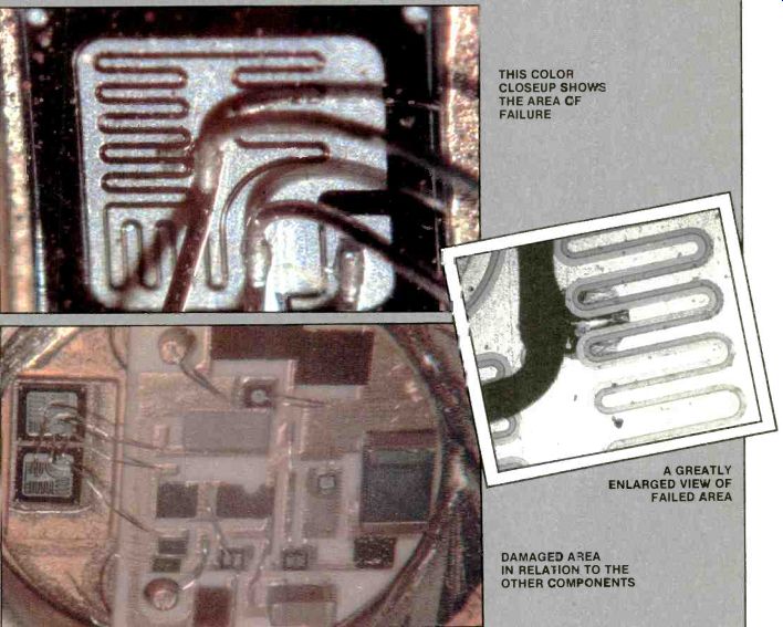
-- Figure 4 These photos show three views of a hybrid voltage regulator
with failed pass Transistor (darkened area). THIS COLOR CLOSEUP SHOWS THE AREA
OF FAILURE ; A GREATLY ENLARGED VIEW OF FAILED AREA DAMAGE) AREA IN RELASION
TO THE OTHER COMPONENTS
-----------
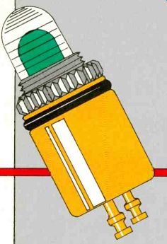
Figure 5. Here is an indicator light with plastic lens.
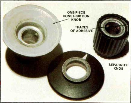
Figure 6. Adhesive problems cause skirted control knobs to separate.
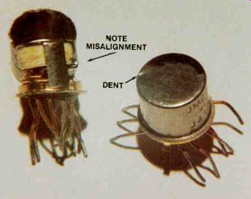
Figure 7. Improper handling has damaged this TO-5 car relay.

Figure 8. Arrows indicate cracks in the epoxy body of tantalum capacitors.
Semiconductor devices
Everyone should be well aware of the sensitivity of electronic components to electrostatic discharges.
Not only will devices fail immediately when exposed to these discharges, but they maybe weakened and fail later during field usage.
DOD-STD-1686 and Military handbook 263 are excellent reference materials to set up procedures to prevent electrostatic discharge damage to components and systems.
Cleaning fluids, or even some conformal coatings, can damage component materials. This often leads manufacturers to include warnings in their specification data. Not following these recommendations can lead to early device failure.
Switches
Devices that are not sealed, such as some switches, can become intermittent or freeze because of flux, cleaning solvents or conformal-coating contamination.
The switch shown in Figure 9 became frozen due to conformal-coating material entering the unit.
Capacitors
Aluminum electrolytic capacitors are susceptible to corrosion caused by halogenated hydrocarbon cleaning solvents (Table 2 lists safe and unsafe solvents). The solvents penetrate the elastomer end seals of the capacitor, resulting in a long-term corrosion failure mode, the degree of which is dependent upon operating time, temperature and applied voltage.
Excessive do leakage, electrical open circuits or internal gassing are the failure symptoms. Field failure rates can be 20% or higher.
Figures 10 and 11 show anodic corrosion and a pushed-out end seal caused by internal gassing.
Epoxy end seals are recommended (Figure 12) with exposure time to any unacceptable solvents limited to less than two minutes to prevent degradation of the epoxy barrier. As with the tantalum capacitor example, care should be exercised during device handling to prevent damage to the epoxy seal.
--------
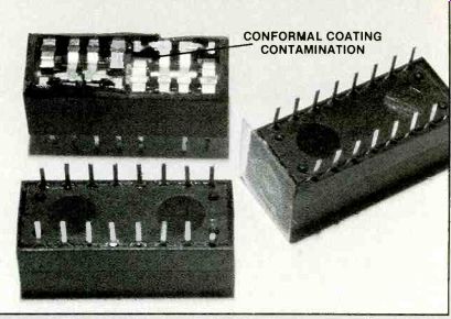
Figure 9. This switch shows corrosion damage from contamination by conformal
coating material.
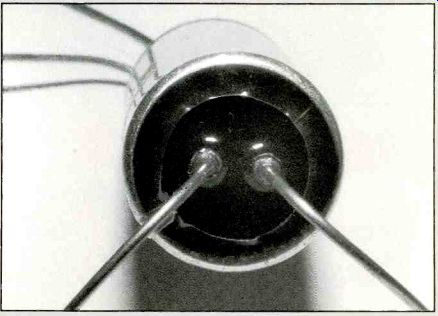
Figure 10. Epoxy seals may be exposed less than two minutes to unacceptable solvents,
to prevent degradation of the epoxy barrier.
SAFE (ACCEPTABLE) CLEANING SOLVENTS ACETONE TOLUOLHEXAN EETHYLACETATE BUTYL ALCOHOL ETHYL ALCOHOL LACQUER THINNER METHYL ALCOHOL MINERAL SPIRITS PROPYL ALCOHOL XYLENE UNSAFE (UNACCEPTABLE) CLEANING SOLVENTS CARBON TETRACHLORIDE CHLOROFORM CHLOROTHENE FREON METHYLENE CHLORIDE PERCHLORTHYLENE TRICHLOROETHANE TRICHLOROETHYLENE
TABLE 2. Examples of safe and unsafe cleaning solvents to use with aluminum electrolytic capacitors.
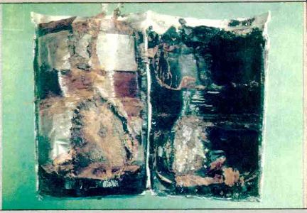
-------- Figure 11. Here, there is anodic corrosion of an aluminum capacitor.
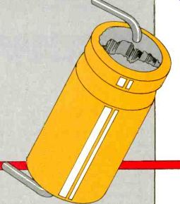
Figure 11. Internal gassing has pushed out the end seal of this aluminum capacitor,
a failure symptom.
Also see: Link |
Scoping TV power supply sources