By Gregory D. Carey, CET
-------------
This is the second of a three-part series dealing with the horizontal output circuits of modern TV receivers. Part I explained how shutdown circuits operate and the best way to find the cause of shutdown.
This time, we will see what happens if the circuits never get started in the first place. Part III will explain how to isolate troubles related to the power supply and regulator circuits. Combining all three should help you isolate any problem related to the output stages.
-----------
We started this series by discussing shutdown problems because some technicians blame the safety shutdown circuits any time they are missing high voltage in a TV receiver. Let's start disarming this myth with a very simple axiom: You cannot have a shutdown without startup. This rule may be so important that you will want to hang it above your workbench.
The reason I am stressing this point so hard is that you use different methods to isolate startup problems than you use to isolate shutdown problems. For shutdown troubles, you want to reduce the voltage so that you can monitor the response of the safety sensors as you gradually increase the supply voltage. You isolate startup problems by helping some circuits along while monitoring a key test point. But you need to understand the startup circuits before the troubleshooting processes really make sense. For the most part, you need to remember that the circuits form a closed loop.
The closed startup loop
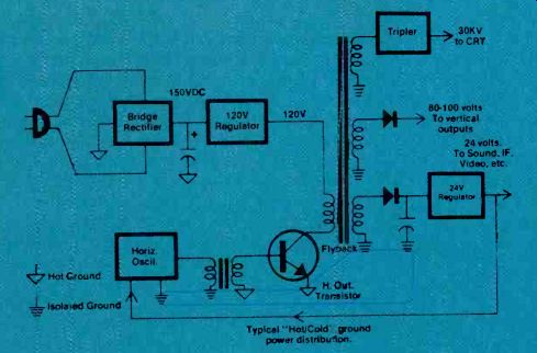
Figure 1 shows a general block diagram of a modern horizontal circuit. Raw ac voltage is applied directly to a rectifier-usually a full-wave bridge. The output is filtered with a large electrolytic capacitor and then fed to a regulator.
(The different types of regulators will be covered in part III.) The regulator feeds one end of the primary of the flyback, which in turn feeds to the collector of the horizontal output transistor.
The output transistor receives its signal from a driver transistor feeding a step-down transformer. The transformer increases the current fed to the output stage to make up for the relatively low gain of the power-output transistor (beta generally runs under 10). The driver transistor gets its signal from the horizontal oscillator. The oscillator and driver, in turn, receive power from a scan-derived power supply connected to one of the secondary windings of the flyback transformer.
If you study this diagram for a moment, you'll soon discover it won't work. The horizontal oscillator cannot run without power from the flyback. But the flyback can't receive power unless the output transistor is being driven by the oscillator. Turning on the power switch gets everything ready, but the horizontal circuit can't get started without a push. That's why you need a startup circuit.
The startup circuit gives the horizontal oscillator and drive circuits the little push they need to start running. When the output transistor begins to conduct, a voltage begins to build in the secondary, feeding the scan-derived power supply. This, in turn, begins to power the oscillator and the driver to provide more drive for the output. After a few cycles everything has built to maximum, and the closed loop is ready to sustain its own operation.
Most receivers use one of two types of startup circuits. The type used generally depends on whether the entire chassis has a single hot ground (referenced directly to the ac line), or whether the chassis has a hot and a cold (isolated) ground. The two circuits are the trickle and the kick start circuits.

Figure 1. The scan-derived power supply and the horizontal oscillator form
a closed loop; the flyback cannot generate power until the oscillator is running.
(Courtesy of Sencore).

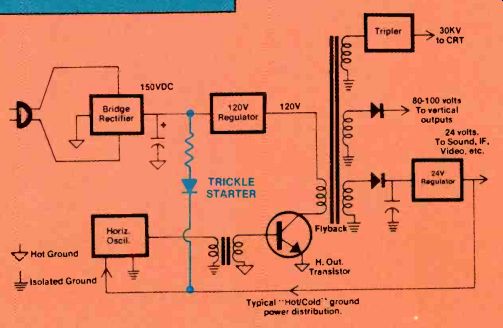
Figure 2. A trickle starter provides a small amount of unregulated voltage
until the scan-derived power supply develops enough power to operate the horizontal
circuits. (Courtesy of Sencore).

Figure 3. The current through the startup SCR (SCR-901) and the current-limiting
resistor (R-905) provide power to the 47V line until the scan-derived voltage
coming through the diode on the flyback (Y957) produces adequate power. (Courtesy
of GE).
Figure 4. This simplified schematic of a circuit used by RCA shows how a
kick starter develops an output. The start transformer produces an output,
but only during the time that the main filter capacitor (C1) is charging.

Figure 5. Here is the actual startup circuit used in RCA models from the
CTC85 through the CTC101. The start diodes (CR302 and CR305) rectify the output
during startup, and then block the flow backwards through the secondary when
the output circuits are running. (Courtesy of RCA)
The trickle starter
The trickle starter, shown in Figure 2, is more common and less complicated than the kick starter. In its simplest form, the trickle starter uses a high-value resistor connected between the unregulated power-supply output and the horizontal oscillator and driver.
This resistor lets enough current leak through from the raw B + circuits to let the horizontal circuits start, but does not provide enough current to sustain operation.
When the scan-derived power supply develops enough power, it takes over from the trickle circuit to operate the horizontal circuits.
You might wonder why the designer even bothers with the scan-derived feedback power. Why not reduce the value of the startup resistor and allow the oscillator and driver to be powered directly from the raw power supply? The answer is that this supply is not regulated.
Line voltage fluctuations, perhaps caused by the refrigerator starting or by a motor kicking in at a factory down the road, could throw the horizontal oscillator off frequency. If flyback power is used, these surges are eliminated by the output stage regulator. Figure 3 shows an actual trickle startup circuit used in a General Electric set.
Kick starters
The startup voltage only needs to be present for the few milliseconds needed for the horizontal circuits to start. The kick starter provides these few milliseconds of power, and that's all.
The popularity of kick starters comes and goes, depending on circuit grounds. The circuit is usually found in receivers that have most of the circuits isolated from the ac line by the flyback transformer.
These receivers still have a hot ground in the output stage. The trickle starter cannot be used in these receivers because the raw B + is on the hot side and the horizontal oscillator is on the cold side of the flyback. The kick starter bridges between the hot and the cold sides of the flyback transformer without defeating the isolation.
A common example of the kick starter is found in RCA chassis from the CTC85 through the CTC101. These receivers have a startup transformer between the bridge rectifier and the main power-supply capacitor, as Figure 4 shows. This transformer mystifies some technicians because dc flows through its primary, and we all know that a transformer cannot be used with dc. Yet the transformer produces enough voltage to start the horizontal circuits. How is this possible? To solve the mystery, you have to think of the circuit before the power is turned on, not after the set has run for a while. At this time the main filter capacitor will be discharged. The starting pulse forms as the capacitor is charging.
The secondary voltage drops to zero when the capacitor is fully charged and dc current is flowing through the primary winding.
The diode at the output of the secondary serves two purposes. It acts as a rectifier while the starting pulse is formed. It then becomes reverse-biased as the scan-derived voltage builds, preventing the transformer from loading the scan-derived supply. (See Figure 5 for an actual kick-start circuit used in an RCA CTC85 chassis.) The kick starter creates one particularly annoying problem for the servicer: It only fires one time.
This gives you only one chance to determine what took place. And it must be reset by discharging the capacitor before it can fire again.
The capacitor may take several seconds to discharge because a dead output stage does not draw normal current. It's a good idea to measure the do voltage at the capacitor and wait until the voltage drops to about 20V before turning on the set again. That way you know the starting circuits can produce the starting pulse.
Circuits that prevent startup It should be pretty clear that the receiver cannot start if the startup circuits are defective. However, the startup voltage can be present, but may not have enough energy to get the output circuits up and running. In still other cases the startup circuits work correctly, but a problem in some other circuit prevents the set from starting.
These defects are also correctly labeled "startup" problems.
A defective horizontal oscillator, for example, prevents startup. The oscillator may be dead, or it may simply be too far off frequency.
Sometimes a bad capacitor or misadjusted hold control can cause intermittent startup.
A set is more likely to have startup problems when it is connected to an isolation transformer. The core of the transformer softens the starting surge and shortens the time the kick starter circuit supplies voltage. The oscillator maybe just far enough off frequency that it cannot get started during the shortened starting pulse.
A defect in any other part of the feedback loop also prevents startup. Common defects are in flyback transformers, output transistors or driver transformers. The receiver will also not start if the primary power supply is defective.
WARNING---Always use an isolation transformer when servicing startup problems to prevent death or injury to the servicer or damage to the circuits. TV receivers that use startup circuits almost always have hot chassis, in which some or all the circuits are referenced directly to the ac line.
NEVER plug more than one unit into an isolation transformer simultaneously. Doing so ma defeat the isolation.
Identifying the problems
The first step to fixing a problem is deciding whether the receiver has trouble in the startup or in the shutdown circuits. You need to know if the horizontal output circuit operated even for a few milliseconds. If some kind of signal appears, you know that the circuits started up and were then shut down. If there is no signal, you treat it as a startup problem.
Some technicians depend on the crackle of high voltage building on the CRT to make this decision. If you hear the high voltage come up, you know that the circuits ran for at least a moment. But the opposite does not always confirm a startup problem because there may be no crackle if the CRT cathodes don't conduct or if the CRT already has high voltage on it from a prior startup. (Note: The flybacks in many modern receivers do not have a high-voltage bleeder resistor, so high voltage may remain on the CRT for a long time.) A better way to tell whether the circuits started is to monitor a test point when you first apply power.
The collector of the horizontal output transistor gives the best information if you have an oscilloscope capable of measuring more than 1,000 volts. As an alternative, you can connect a high-voltage probe to the CRT high-voltage connector to see whether any high voltage develops. We will cover the test at the output transistor because it provides more information.
WARNING---Use extreme caution when making any measurements around high voltage. Remove the power before making connections.
Make certain none of the test leads can come loose during a reading. Be especially careful to properly ground your test equipment to the circuit.
Turn off the set and connect your scope probe to the collector of the horizontal output transistor.
Be sure to securely attach the ground lead so it cannot come loose during the test. Preset your scope to measure the flyback pulse from the output transistor. This pulse normally runs between 700Vp-p and 1,200Vp-p so set the input attenuator to its highest voltage level.
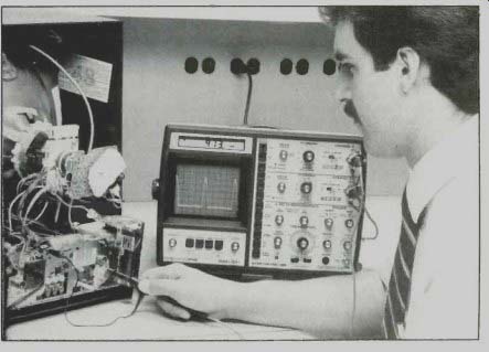
Set the sweep to the horizontal video rate. Use your "horizontal preset" function if your scope has one, or else set the timebase switch to the 10 microsecond per division rate. (See Figure 6.) Now, watch the scope's CRT as you turn on the set. If you see pulses build--even briefly--you know the circuits started and were then shut down. Follow the procedures in part I of this series to find the exact cause.
If you don't see pulses, switch your scope to measure do (either by pressing a digital readout button or by going through the steps needed to make a do measurement with the CRT). If the voltage shows zero, your "startup" problem is really a power-supply problem. Move back through the regulator and supply circuits to find its cause.
If do is present, the rest of the circuits may be waiting for the startup pulse. You need to test the startup circuits next. One way to do this is to substitute for the startup voltage.
Give the set a little help
An effective way to check the startup circuits and scan-derived power supply is to substitute for the startup voltage with an external power supply. This is especially important when working with the more complicated kick starters. If the circuits start, you will disconnect the external voltage to see if the circuits continue to operate.
Monitor the collector of the output transistor (or the high voltage) to see if the circuits respond. Adjust your external power supply for the dc voltage normally found at the scan-derived supply that feeds the horizontal oscillator.

------ Figure 6. The best place to monitor, when confirming whether
the set started, is the collector of the horizontal output transistor. If
you see pulses build and then collapse, you know that the set started and
was then shut down by a safety circuit.
Connect the ground lead to the circuit ground. Turn on the power to the TV receiver and touch the positive lead of the external power supply to the test point in the receiver.
If nothing happens, the startup circuit is not the trouble. You will now need to track down the problem. The output stage is often damaged by power-line surges or nearby lightning strikes, so start there. Use a transistor tester to check the output transistor, and use a reliable yoke/flyback tester to test the flyback. If the output components test good, suspect a problem in the horizontal oscillator or the driver circuits.
If the receiver starts and runs with the external power supply connected, you're almost finished.
But you still have to see if the set will continue to run. Disconnect the external power-supply lead. If the set still runs, you know that the closed loop functions correctly, but cannot get started. Test the items mentioned earlier: the startup circuits and the horizontal oscillator's free-running frequency.
(Don't forget that you will have to wait for the filter capacitor to discharge to re-check the operation of a kick starter.) If the set shuts down with the external supply disconnected, you have confirmed that the scan-derived power supply is not delivering enough power. Check the rectifier diode. If it is had, be certain that you replace the diode with the correct type, because diodes designed for 60 Hz supplies often don't work correctly when rectifying the 15kHz signals from the flyback. If the diode is good, suspect an open flyback winding or a component or connection between the flyback and the horizontal circuits.
Separating startup problems from shutdown problems will help you get to the real cause of a high-voltage problem faster. When you're certain you have a startup problem, the correct troubleshooting procedures help you quickly isolate its cause.
Also see:
What do you know about electronics?--Model behavior
Report from the test lab: the Semi analyzer transistor/junction tester.