
By Howard Falk
[This is an adaptation of an article by Falk, a free-lance writer and former electronics magazine editor who has published several books and articles about using personal computers.]
When you're designing a circuit, after you sketch it out your next steps are probably to make a few rough calculations, then start to build a breadboard. When the components are connected and the power is turned on, you get your first look at what has to be changed to actually make the circuit work.
If you have a personal computer, however, there may be a shortcut that can take you directly from your sketch to a reliable, working circuit. With inexpensive circuit design software, you can type in descriptions of the components you are using and the way they are connected to one another. The software will then calculate the performance you can expect from your circuit. If it does not meet expectations, you can do additional computer runs, changing component values until you get the de sired results.
You don't have to write any computer programs to get these results. What you must do is learn to use one of the commercial computer-design software packages that are currently available. That will take some time and effort, but it is well within the grasp of anyone who can put together a working electronic circuit.
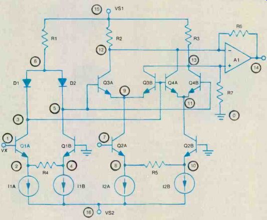
Figure 1. This ratio multiplier circuit, simulated by the ACIRC package,
has 16 nodes (see circled numbers). Each of the input code lines that describe
the circuit for ACIRC contains information on node connections and operating
parameters for one of the components.
Simulated circuits
If you think software packages that sell at reasonable prices have only trivial capabilities, think again. These packages typically can handle circuits with 30, 40 or more nodes. (A node is simply a connection point for two or more components.) Take a look at the 16-node ratio multiplier circuit shown in Figure 1. It includes eight transistors, two diodes and an operational amplifier. A program with a 30-node capacity can handle circuits approximately twice as complex as this one.
The calculated results these packages will produce include dc circuit parameters such as voltages, currents and power for all components or for selected components. These results allow users to determine immediately needed power and voltage ratings for components, as well as power supply requirements.
Packages designed to simulate ac performance go further. For in stance, with ACIRC, offered by FB Circuit Products, the signal (sweep) input to the circuit being simulated can be specified by an initial and final frequency, an initial frequency step, and a multiplier that selects linear or logarithmic sweep. To excite the circuit with a single frequency, the user simply sets the initial and final frequencies to the desired value. The package then calculates results such as voltages, phase angles and gains at nodes or across branches.
Don't expect instantaneous answers from these circuit-design packages. The computations they go through are often very complex and lengthy. Results for a typical 40-node circuit calculated by the ACAP package will take an IBM personal computer a full 40 minutes to complete.
Components on tap Circuit--simulation packages recognize and use only certain types of components. All the simulation packages make avail able passive components such as resistors, capacitors and inductors, and all allow use of voltage or current sources, or both. The ACIRC package also provides for use of transformers in circuits.
In addition to limits on the number of nodes a package will handle, there may also be specific limits on the number of each specific type of component that can be used. Users of the DCNAP software package from BV Engineering are limited to no more than 70 resistors, 30 inductors, 30 capacitors, sources, independent current sources and 30 dependent current sources. The total of all components in a circuit simulated by DCNAP must not exceed 200. The numbers differ for other packages, but most of them also have their component limits.
With some of the packages, like ACAP (from DYNACOMP), DCNAP and ACNAP (from BV Engineering), users have to con struct their own models of transistors and other active devices using combinations of the circuit elements the package recognizes.
(See Figure 2.) The ACAP manual shows suggested models for op-amps. (See Figure 3.) Other packages come with active device models that can be called from storage and inserted into circuits as components. For example, the DCIRC and ACIRC packages (both from Circuit Products) come with simple models of transistors.
FETs and op-amps.
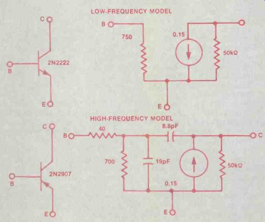
Figure 2. Low- and high-frequency transistor models must be made up of components
recognized by the ACNAP package.
The CircuitPro package (from E/Z Cad) analyzes circuits with as many as 120 to 150 transistors and comes with ready-to-use models for 48 industry-standard diodes, 35 bipolar transistors and seven types of operational amplifiers. The models are quite realistic. For ex the op-amp models include almost all the first- and second-order characteristics found in real-world amplifiers. (See Figure 4.) Users can also define their own …
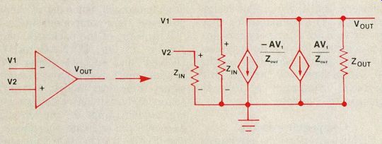
Figure 3. The manual for the ACAP package recommends this model for op-amps.
Models such as these are created by the user. Here resistor and current-source components are calculated and specified by the user. The quantity A is the gain of the op-amp models for other devices and list them as sub-circuits, which can then be used, by name, as standard elements whenever needed. Most elements also have model parameters that can be used to define the shape of their characteristic curves.
Checking worst-case scenarios An important feature, offered by many of the packages, is simulation of the kinds of variations that can be expected in components.
When a circuit is built, component values will be defined within tolerance ranges. A 5,000 ohm resistor with a 20% tolerance may actually have a resistance anywhere between 4,000 ohm and 6,000 ohm.
The ACAP package takes a simple approach. It calculates the mean and standard deviation of selected node voltages, based on the component tolerances. These statistical results give the user some idea of the limits of performance that can be expected due to component variations.
Another approach is to allow users to simulate the changes in output that will result from a small change in the value of a component. The ACNAP package uses this kind of sensitivity analysis to reveal the amount by which the magnitude and phase of the output will be affected by a 1% change in the value of any component.
ACNAP also has a Monte Carlo analysis feature that randomly varies component values within their specified tolerances. Results indicate the statistical limits of the circuit responses.
Such calculations can be extremely valuable, particularly when many copies of a circuit will be fabricated. However, users must be prepared to wait patiently while the software threads its way through the computational complexities. DCNAP, which has sensitivity and worst-case analysis capabilities similar to those of ACNAP, ran a typical sensitivity analysis for a 4-node circuit in 107 seconds. A worst-case analysis for the same circuit took 81 seconds.
Obviously, run times for analyses of larger circuits will be much longer. With ACAP, it may take 10 or more iterations of the statistical calculations to get ac curate results.
Figure 4. Input statements to describe and simulate a bandpass filter circuit with the CircuitPro package are shown above. At the top right is an "op-amp macro model" that is used three times in this circuit. The circuit itself, with node numbers circled, is shown at the right center. At the bottom right is the output for gain and phase from 7,000Hz to 13,000Hz, as plotted by CircuitPro.
Extras and errors
Some of the packages have important extra features. For example, the ACNAP package uses the desired frequency range and the number of integration steps to calculate the noise equivalent bandwidth. (See Figure 5.) ACNAP can also produce a file that allows computation of the circuit's time-domain response, al though the file has to be processed by a separate signal processing package from the vendor.
The DCIRC package caters to users who want to accurately fine tune output based on component parameters. (See Figure 6.) The user adjusts the parameters, then gets a rapid display of output results on which to base further adjustments.
Users will inevitably make errors as they try to get these packages to solve circuit-design problems. Unfortunately, most of the packages do not provide convenient ways to handle and correct such errors. Some provide no error messages at all; others, like DCNAP, make some effort to do so. DCNAP is designed to recognize certain errors, such as numbers, components or nodes that are called for but do not exist in the circuit description. If the user makes one of these errors, the package will display the warning "ILLEGAL ENTRY, please try again." When other errors such as running out of disk storage space occur, the package is not so lenient, and the user has to start all over from the beginning of the pro gram sequence.
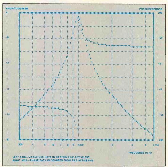
Figure 5. This bode plot for a bandpass amplifier, produced by the ACNAP
package, shows the magnitude and phase response of the circuit over a defined
frequency range.
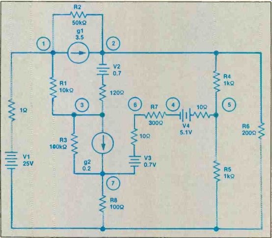
Figure 6. This voltage regulator circuit, laid out for simulation by the
DCNAP package, uses the two dependent current sources, R2, V2, R3, V3 and
the 120 ohm and 10 ohm resistors to model two transistors. Nodes are shown
as circled numbers. For this package, the ground node is always numbered 0.
In ACNAP, error messages are 2-digit numbers; the user refers to a list in the manual to interpret them. In some cases the package simply refuses incorrect input and returns the user to the previous program step. However, the vendor promises to clear up, over the phone, any error situations the user cannot understand.
Finding the right package Most of the effort a user will put into one of these circuit simulation packages will be in the form of keyboarding circuit descriptions.
In the long run, packages with convenient data input facilities are the ones that will be easiest to use.
Input data may be entered one line at a time or may be in the form of an entire input file that users prepare with their own editing or word processing software. In either case, users will have to learn the exact formats that are to be used, including the order and manner in which component names, types, node-connections and other items have to be entered.
If the data is keyed in wrong or the circuits need to be revised, the input may have to be changed, sometimes while it is being entered, often after a complete set of data has been entered. In any case, the data will have to be edited, so the facilities provided by the simulation package for such editing are important.
More or less Most of the packages in the accompanying sidebar are roughly equivalent in price and capabilities. CircuitPro is an exception. It is considerably more expensive than the other packages and is more powerful. At the same time its price, about $1,000, is well under that of the very sophisticated circuit simulation software packages used by professional integrated circuit designers.
Most of the packages can handle five basic circuit elements (resistors, capacitors, inductors, voltage and current sources); active devices often must be modeled with combinations of those basic elements. Other packages also handle active devices.
At the other extreme are the EE1 and EE2 packages. These do no circuit simulation at all. Instead they provide a selection of specialized calculations that can be useful in circuit design. The EE1 includes 17 different calculations for do circuits, of which seven have to do with charge and discharge in RC or RL component combinations. The package does not go so far as to deal with RLC combinations. There is also a table that displays resistances and fusing currents for various gages of cop per wire.
The EE2 package (for ac circuits) offers similar facilities.
Here the calculations include such assorted items as complex number arithmetic and calculations for twin-t filters, skin effect, radiation from a wire pair, bandwidth-rise time and transformers. The wire table is also included in this package.
Circuit-design software ACAP Limit: 40 nodes
Circuit elements: basic five plus conductance, voltage-controlled current sources
Active devices: user–modeled
Functions: node voltages, mean and standard deviation of node voltages, output frequencies, radian frequencies, output in decibels
PC type: IBM/PCs, most other types
Price: under $50 Vendor: DYNACOMP, 1064 Gravel Road, Webster. NY 14580; 716-671-6160
ACIRC Limit: 40 nodes
Circuit elements: basic five
Active devices: transistors, FETs and op-amps
Functions: phase angles, voltages and gains at node
PC type: IBM/PCs and compatibles with 192K main memory
Price: about $100 (includes DCIRC package)
Vendor: FB Circuit Products. 5234 Longfellow Way, Oxnard, CA 93003; 805-986-2276
ACNAP Limit: 30 nodes
Circuit elements: R, L and C components, dependent current sources Active devices: user-modeled
Functions: node magnitude and phase response, sensitivity analysis, Monte Carlo analysis, noise equivalent bandwidth, time-domain response (signal processing package required)
PC type: IBM/PCs and most other types; PC- or MS-DOS requires 256K main memory; CP/M-80 requires 62K; TRS-DOS requires 48K
Price: under $100 Vendor: BV Engineering, 2200 Business Way, #207, Riverside, CA 92501; 714-781-0252
CircuitPro Circuit elements: 15 (basic five plus diodes, voltage-controlled current and voltage sources, current-controlled current and voltage sources, junction FETs, mutual inductors, inductors, MOSFETs, BJTs, transmission lines, independent voltage sources) Functions: frequency response, time response, sensitivity analysis
PC type: IBM/PC/XT/ATs (PC version of the UC Berkeley Spice simulator)
Price: about $1,000
Vendor: E/Z CAD, 5589 Starcrest Drive, San Jose, CA 95123
DCIRC Limit: 40 nodes
Circuit elements: resistors (50), voltage sources (10), current sources (10), diodes (10)
Active devices: stored models for transistors (25), FETs (10) and op-amps (10)
Functions: Voltage, current and power for components; node voltages; input and output resistance; sensitivity analysis
PC type: IBM/PCs and compatibles with 192K main memory
Price: about $100 (includes ACIRC package)
Vendor: FB Circuit Products, 5234 Longfellow Way, Oxnard, CA 93003; 805-986-2276
DCNAP Limit: 30 nodes, 200 components
Circuit elements: basic five, plus dependent current sources Active devices: user modeled
Functions: node voltages; current, voltage and power for circuit branches; sensitivity analysis; worst-case analysis
PC type: IBM/PCs and most others (memory limitations are the same as with ACNAP)
Price: under $100
Vendor: BV Engineering, 2200 Business Way, #207, Riverside, CA 92501; 714-781-0252
Also see:
Troubleshooting the chopper circuit