By Homer L. Davidson [ Davidson is ES&T's TV servicing consultant. ]

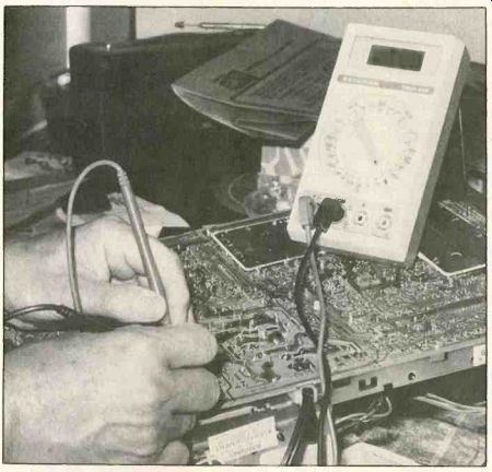
The technician is testing bridge diodes from the bottom of the circuit board. A DMM special diode test is used on the four bridge diodes of the + 150V hot supply.
All servicing technologies described in this article are well known. Many of the tests commonly used (not mentioned in this article) are not recommended for the CTC131. I have included only those tests that produce good results with little danger of damage. The CTC131 is not a suitable circuit for experimentation. Just restore the original circuit; don't change it.
A person can look at a simplified schematic of the CTC131 chopper system and think, "That circuit isn't so difficult; I can understand how all of it operates." Very true. But that is only because it has been greatly simplified; the complete circuit is nearly incomprehensible.
Many resistors were added for voltage drops and current limiting. Diodes were added as switches, as rectifiers and as vari able resistors. Many capacitors from small to large capacitance were included for a variety of tasks. A close-packed arrangement of capacitors, resistors, diodes and zeners completely surrounds U401, the regulator-control IC. Any one of the functions (which usually involves one pin of U401) can be traced and eventually understood, but it is difficult. And the difficulty is in creased by the cross-coupling be tween circuits. My advice when you're servicing this power supply is to use the full schematic.
The largest addition to the chop per's simplified schematic is U401, the regulator-control integrated circuit. The following are several of its functions:
Monitor the high voltage (HV) and shut down the chopper if the HV rises too high.
Monitor the + 129V supply, using it to regulate the do voltages produced by the supplies powered through T105.
Monitor the + 12V supply.
The pulse-width-modulation system produces the variable-width pulses that are emitted from U401 at pin 4. These pulses are rectified for the regulated power supplies.
An internal oscillator is locked to the television horizontal scanning frequency to avoid beats.
Regulation in this type of system is accomplished by varying the pulse widths. When narrow do pulses are integrated, the result is a low dc voltage. As the width of the pulses increases, the do output voltage increases proportionally.
Voltage regulation in the CTC131 can be summed up in this statement: When a higher de output voltage from T105 is needed, the chopper pulses are widened, producing a higher de output voltage.
Complete servicing of the CTC131 chopper and power supply circuits is a complicated procedure. Fortunately, many repairs can be performed after simple measurements and the replacement of a few components.
In most TV receivers, the horizontal-drive and horizontal-output transistor areas receive most of the attention during preliminary testing. This is not the case with the CTC131, where the chopper stages are the most likely to fail; therefore most of the tests involve the chopper.
The power-makers (and thus trouble-makers) are shown in the block diagram. They should be the first tested when F100 in Figure 1 is found to be blown.

Figure 1. Most of the CTC131 hot 120 Vac wiring is contained in the circuits
and components inside the area bounded by the lines of large rectangles or
blocks. All other wiring uses cold grounds.
This schematic was carefully arranged so the areas of hot ac V wiring and cold ac V grounds are clearly differentiated. Everything inside the dotted rectangle is hot.
Notice that each of the four transformers has one or more hot acV grounds on one side via one or more windings, but they also have cold acV grounds at the other side of the same transformer. This is not a new application for transformers. Power transformers, with 120Vac on one side and several secondary windings, became popular. These cold chassis models were greeted many years ago as a major advance in safety over the methods of using rectified 60Hz power without isolation.
Actually, all the CTC131 60Hz wiring (less the degaussing circuit and the tuner power) is contained in the center area of Figure 1.
Remember that T101, T105, T103 and T104 are the four transformers with hot primaries and cold secondaries.
Because there is so little 60Hz hot wiring, it appears out of balance to give that much detail about the subject. Yet it always has been part of RCA service meetings. Therefore, hot/cold grounds must be important. Although the CTC131 is not the first RCA to have hot/cold double grounds, it is much more complicated.
An incorrect connection for a quick test on this set is more likely to cause damage than a similar mistake with an older model (one without a chopper).

Figure 2. These components are sufficient to make up an operable circuit,
although many of the less important resistors and capacitors have been deleted.
0100 and 0101 have the largest failure rate of all components.
Circuit descriptions
If you work with these CTC131 chassis without studying the circuitry, the relative failure rate might seem to indicate that the chopper transistors are weak or are just prone to shorting out.
Many of the failures end with the Q101 chopper transistor shorted between all pins. Unless some other components are replaced, the new transistor will be ruined almost instantaneously when power is next applied.
Did you know that the chopper is forced to control the largest amount of power of any transistor in the chassis? The output of the chopper supplies four de voltages.
One of those voltages is + 129V, which is the regulated B + for the horizontal-output transistor's collector. The other chopper-regulated voltages (+ 24V, + 16.5V and- 24V) power most of the circuits remaining, helped in a small way by two B + supplies rectified from flyback transformer power.
A full list is not necessary to see that the power load carried by a chopper transistor is much higher than that of any horizontal-output transistor. Later, the circuit and components that reduce the dissipation of the chopper will be discussed.
The schematic condensed
Several items should be discussed before leaving Figure 1.
Notice that there is no on/ off switch on the schematic. That's because there is none for the TV function.
The 120Vac is applied continuously, and the + 150V voltage is also present, waiting with zero current and maximum voltage for the chopper channel to be activated.
T101 is called the standby trans former because it operates 24 hours a day to power the tuner-
control module, even when the television is off. It is a small transformer, mounted on the chassis at the rear. The windings will feel warm after several hours of operation. (T101 is not shown in any of the photos or schematics.) Also, ac power is taken from the cold T101 secondary. After rectification by CR406 and filtering by C463 (220µF), the result is a stable + 12.3V that is always available.
This + 12.3V source powers the oscillator and other essential sections in U401. Without it, start-up would be impossible.
Some of the following can be checked only by studying a complete schematic. When the front panel on/off button or the remote control on/off button is pressed, the tuner-control module delivers a logic low that reverse-biases CR426 in the overcurrent shutdown circuitry. This starts the power supplies and chopper into operation. However, the low is just a short pulse, and the operation would soon stop except for + 30V, which is produced by rectification of flyback pulses. A sample of the + 30V is fed to the tuner-control module and a certain IC that latches the on/off line to a steady logic low state. This information is not shown in Figure 1, but we mention it here to explain how the television can be turned on without a conventional switch. (The chopper area in Figure 1 is explained in detail later, along with accompanying schematics. Therefore, the explanations will be general in nature until then.)
The width of the pulses produced in the pulse-width modulated (PWM) area of U401 undergoes constant changes as part of the regulation process. The pulses then exit at pin 4 before being sent to the base input of Q401, the chopper-driver transistor.
The next stage would appear to be a normal transformer-coupled amplifier except for turn-off transistor Q100. Notice that Q101 is the only load connected to the hot + 150V supply. After diode rectification and filtering, four secondary windings on T105 produce three major B + and one negative supply. (These are discussed later.) Also, the bridge rectifier consists of four separate diodes.

Figure 3. Fuse F100 (5A) and R109 (2.70) will be blown by excessive 120 Vac
current. Resistor R109 is a special number and is soldered into place, so it
is best to find the problem with the 120Vac power turned off, if possible.
Test all four bridge diodes in-circuit for both forward conduction and reverse-polarity
leakage, then continue the tests.
Figure 4. Circuitry between Q101, T103 and Q100 is the center of attention because most of the chopper-component failures occur here. If Q101 is shorted, test R102 and R106. If they are open, the new Q101 installed will be destroyed in a fraction of a second after power is applied.
PWM and the chopper
As shown in Figure 2, the PWM chopper-regulated power supply consists of three transistors, three transformers and one IC regulation control.
Values of a paralleled resistor and capacitor at U401 pin 3 deter mine the free-running frequency (about 15kHz) of the regulation control RC oscillator. Locking is accomplished by horizontal pulses brought from T401 flyback to U401 pin 8. The locking is necessary to prevent beats and interference that could occur if the frequencies were different and the chopper signal radiated into the television signal circuits.
At U401 pin 4, the output signal of the regulator control (which consists of segmented, variable-width pulses) is capacity-coupled to the base of Q401, the chopper driver transistor. Following amplification in Q401, the waveform from interstage transformer T103 is applied to the Q101 chopper out put's base. Also, Q100 has a function, as explained later. The Q101 chopper collector is connected to the T105 chopper transformer, and the pin 2 end of the T105 winding connects to hot + 150V (nearly the only load on the + 150V supply).
According to scope waveforms, the theoretically perfect square-cornered do pulses at the Q101 collector are more like rounded pulses. These rounded pulses pass easily through transformer T105 primary, producing voltages in the four secondary windings. (See Figure 2.) The highest do voltage is + 129V, which supplies the horizontal-driver and horizontal-output transistors with de power.
Also, the + 129V is used in the vertical-output stages. A sample of this voltage is provided to the voltage comparator inside U401 for regulation and shutdown in the event of excessive high voltage.
This + 129V is rectified by diode CR412 and filtered by capacitor C443 (2µF).
The winding between T105 pins 4 and 5 produces + 24V after rectification by diode CR415 and filtering by 2,200µF C452. The +24V source powers the audio-output stage and all the remaining sections of the vertical sweep. The winding between pins 3 and 7 produces + 16.5V after rectification by CR414 and filtering by 680µF C456. The + 16.5V supply furnishes power for most of the signal-processing circuitry, the audio circuits and a few other tasks. Also, by zeners and a voltage regulator transistor, the + 16.5V supply is parent to + 12V and + 11.2V source 1, source 2 and source 3.
That terminal 3 to 6 winding has the ground at the top, implying that the polarity is reversed, which is correct, because it is feeding a negative supply. After rectification by reversed CR416 and filtering by 220µF reversed C451, - 24V is produced. The- 24V source is used mostly as a reference for the automatic kinescope-bias circuitry. Evidently, very little current is needed.
Overcurrent shutdown in the CTC131 is much more complicated than it is in most television receivers. Emitter current of the Q101 chopper-output transistor is passed through the primary of transformer T104, with 112 resistor R107 paralleling the primary before the current returns to hot ground. The transformer secondary signal is filtered and amplitude-reduced before it joins the part of the circuit that is used for turn-on (when CR426 is low).
From there the combined signals go to U401 pin 9. Notice that all the circuits from the secondary of T104 on to pin 9 have cold grounds. When the Q101 current exceeds a certain value, the over-current shutdown circuit is activated and the chopper operation ceases.

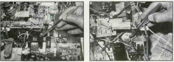
T105, the chopper-output transformer, is pointed out by the end of the pen.
Q101 is mounted just to the left and on a vertical panel, with the Q101 terminals
and socket side shown.
Q101, the chopper-output transistor (pointed out by the pen), is mounted on a vertical panel, so this is the view from about the center of the chassis. The socket and pins are on the other side.

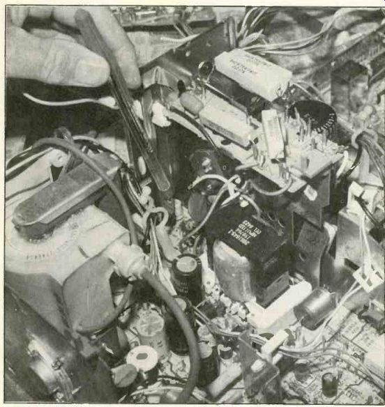
The chopper turn-off transistor Q100 is located at the end
of the pen. Q100 is soldered to the circuit board. All chopper transistors
(including Q100) should be replaced only by new ones with original part numbers.
Chopper turn-off operation
Mention was made previously of the turn-off operation. Here's how Q100 operates. (Refer to Figure 2.) CR108 and 3.311 R102 are in series between the Q101 base and the top terminal of T103's secondary winding. When that top terminal is positive, CR108 will con duct through R102 and present a turn-on current to the Q101 base.
At the same time, an instantaneous negative voltage from the bottom terminal forces CR105 to con duct, and this charges 220µF C114 with about- 2V relative to the Q101 emitter. (Notice that the positive lead of C114 connects to Q101's emitter.) When polarity of the input/drive voltage reverses, diode CR108 conduction is turned off, and the polarity of the bottom terminal forces the emitter/base junction of Q100 to become forward biased.
Therefore, Q100 saturates, producing reverse current flow through R106, which removes the stored charge in the emitter/base junction of Q101 to make certain that the Q101 transistor current turns off quickly.
If the receiver is operated when the Q101 chopper has a problem in the Q100 area, Q101 will heat up excessively. Above a certain over load point, the transistor will short and the 5A fuse (F100) will be blown. Unfortunately, by this time several components are likely to have been damaged. The critical ones are: R106, R102, R103 and CR108, plus transistor Q100 chopper turn-off. Of course, the Q101 chopper transistor carries the largest load and is subject to external overloads that cause Q101 to short.
Common symptoms
If the symptoms are no picture/no raster, measure for the + 129V collector voltage at the body of the horizontal-output transistor. This shows whether or not the chopper power-supply circuits from T105 are normal. If zero (or very low) do voltage is measured at the horizontal output, test the Q101 chopper-output transistor collector voltage at the case. (Remember, the negative test probe must be touching the hot negative terminal. The correct voltage is hot + 150V, but if the chopper case checks zero volts, or much lower than + 150V, test the four diodes of the bridge rectifier.
A convenient hot ground for these tests is the negative terminal of C105. Notice that the + 150V tests to hot ground, but the + 129V sup ply tests to cold ground. Specific tests for the bridge diodes are sup plied later, along with additional schematics. And of course, the four basic de voltages produced by rectification of T105 pulses can serve as checkpoints where a few minutes spent in testing can pro duce at least four voltages for analysis. These checkpoints are:
TP400, TP401, TP402 and TP404. (See Figure 2.)
Figure 3 shows such major components as the bridge rectifiers, the F100 fuse, and the R109 surge-limiting resistor. The fuse and resistor usually must be replaced any time a shorted Q101 chopper-output transistor is replaced.
Both the fuse and limiting resistor are there for protection (although the resistor has other functions). Therefore a list of combined symptoms can be helpful. For example:
Sometimes when the chopper transistor is only leaky, the fuse will not blow.
A shorted Q101 chopper output and a shorted horizontal-output transistor occurring at the same time will blow the fuse and R109.
Usually both the fuse and R109 will be opened by overload from a shorted or leaky bridge diode, or a shorted Q404 horizontal-output transistor along with a shorted flyback transformer.
A low-resistance reading across filter capacitor C105 in the + 150V hot source often indicates a shorted Q101 chopper transistor.
Measure the resistance from the body of Q101 to chassis ground (and also hot ground). Then remove the chopper Q101 output transistor from the circuit and make the same measurement again. If the second reading is much higher, this could indicate leakage in Q101. Next, test Q101.
A diode tester or the diode function of a digital multimeter can be used to test individually each silicon diode of the bridge. In addition to the usual hazards of large-current diodes, these diodes might be damaged by weak lightning strikes or strong overloads (such as a shorted Q101 or horizontal-output transistor). These bridge diodes could become shorted or just leaky.
For an accurate test of diode leakage, disconnect one lead of the diode during the tests. If the DMM gives any hint of leakage, change to a VOM on a higher-resistance range. This reverse-polarity leakage-resistance reading should be very high for these diodes. If there is doubt about a diode, replace it. Use 3A rating diodes for replacement. (Incidentally, if the RCA 2.70 15W R109 resistor cannot be obtained, re place it with two paralleled 5(2 15W resistors. However, the genuine article is recommended.)

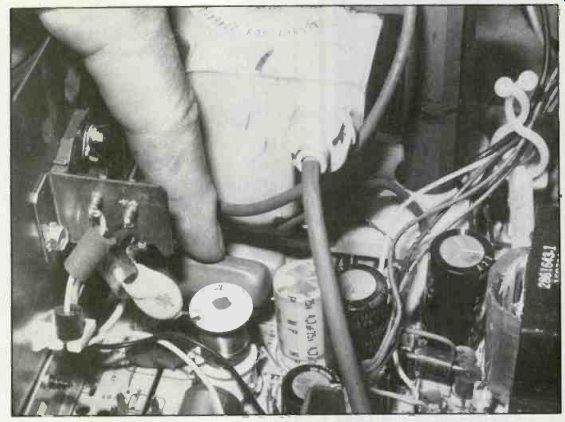
--- C438 (which the technician is pointing to) is a part of the horizontal-output
circuit.
When C438 is shorted or severely leaky, it might destroy Q100, Q101, Q404 and U400.
Finding the components
Here are the locations of these input ac circuit components: R109 is mounted high on the degaussing board; fuse F100 is plugged into snap clips near the back at about the center of the chassis (easy ac cess); the large C105 filter capacitor is near the right-to-left center and about 25% from the rear of the chassis; and the bridge diodes are scattered in a "southeast" direction on the circuit board near C105.
If the + 150V hot supply at the Q101 collector measures almost zero voltage (compared to hot ground), but the four bridge diodes have been tested and finally replaced with new ones without improvement, then where do you look? Few components remain untested.
Assuming that you have tested C105, two items remain untested: continuity of the power wiring and the actual 120Vac line voltage.
Figure 3 shows all the basic ac wiring except the noise filter, L102.
Unplug the power and check the power wiring with an ohmmeter.
Then, reconnect the power and check for 120Vac using the DMM ac function. The 120Vac must reach CR100 and CR101 cathodes where the voltage can be measured.
When the fuse continues to blow If you've done everything you can think of to repair the set, but the fuse blows every time you turn the set on anyway, here's how to protect the fuse and the TV circuitry while you probe further.
Remove the fuse from its holder and connect a 100W incandescent light bulb in its place. The resistance of the bulb limits the current that the television can draw to a safe level, while its brightness gives you a visual indication of the amount of current being drawn: If the bulb is bright, the television is drawing high cur rent; a dim bulb means the current draw is low.
In one CTC131 I encountered, the first test with the bulb/fuse showed a bright bulb. I removed the horizontal-output transistor mounting screws (to disconnect the B+) and the light became very dim. These symptoms pointed to serious problems in the high-voltage and deflection sections.
If the test just described results in a bright bulb during both conditions, the next step is to remove chopper-output transistor Q101. If the bulb then becomes dim, Q101 is shorted or something is drawing excessive current from one of the four T105 voltage supplies.
If the bulb remains bright and no obvious defects are found, the next step is to check all four bridge diodes; DMM and VOM tests of the diodes were described earlier. Certain types of diode leakage vary with the applied voltage. There fore, a VOM often would show a leakage reading where a DMM would not. An initial test of the diodes can be made in-circuit (without disconnecting any leads).
Of course, replace any diodes that show leakage.
Also, check the resistance of C105; it might be shorted or leaky (notice the hot ground).
Problems in T105 voltage supplies In addition to defects in the chopper driver and output stages, it is possible for problems in one or more of the four do supplies powered by T105 to develop from shorted, leaky or open diode rectifiers or filter capacitors. If the overload is heavy enough, it can cause chopper shutdown.
Check the silicon rectifier of each voltage source. This can be done rapidly with the diode test of a DMM. Normal readings for CR413 and CR415 are about 0.458V with overrange readings displayed for the other polarity.
When CR414 is given the diode test, the result might be 0.430V in one direction and 0.650V in the other direction. These test results are normal, because the + 12V regulator provides a low-resistance path in one direction. If there is doubt, disconnect one end of each diode and test the diode as if it is out of circuit.
Resistance readings for tests
Shorted or leaky components in circuits connected to different voltage sources can cause the chopper power supply to shut down or drastically reduce the out put voltages. After you've tested the major components of the power supply, take a few ohm meter readings of the resistances of the various voltage supplies to cold ground. You might discover leaky components in the branch power supplies. The resistances in Table 1 were obtained by a digital multimeter from the test points mentioned. Of course, the other lead of the DMM was attached to cold ground. The readings must all be made with the receiver off.
Any reading of lower resistance than those found in Table 1 night indicate a leaky or otherwise defective component that is connected to the same voltage source. These measurements can be taken from the various test points or from the corresponding diode rectifier. Although these readings might be different depending on the type of meter used, this voltage source-to-ground resistance table could save you valuable time when the chassis is intermittent or overloaded.
During troubleshooting, you must know the DC resistance of various windings. That helpful data is supplied in Tablet 2.
Also see: Locating replacement parts