By Homer L. Davidson
Some flyback defects not only stop the television operation but also leave a trail of burned and destroyed components. This article describes a method of applying reduced line voltage to protect most components while extended testing can be performed. Several case histories are presented.
A defective flyback transformer instantly can destroy any or all of these components: the horizontal output transistor; the low-voltage regulator transistor; various zener and regular silicone diodes; and several power resistors. All might be ruined before a fuse can blow. r Flybacks can develop many types of defect. One might have shorted turns in a winding, and this could not be detected by resistance measurements. If you service a lot of televisions you should have some piece of equipment that includes a ringer, an impedance tester or some other item that is capable of checking inductances. A short from some winding to ground can be formed when the flyback forms a leakage path be tween winding and core, where it cannot be seen. Many models take a voltage sample from the cold end of the high-voltage winding, using it in the automatic-brightness circuit, and often to trigger the safety shutdown circuit from excessive HV current. Occasionally, a fly back will produce this excessive current in the HV winding's cold end, which sometimes activates shutdown. Of course, excessive HV amplitude also will activate the shutdown, and flybacks sometimes produce excessive HV.
---- Most flybacks are mounted near a corner (as this one) or at an edge with the horizontal circuitry around them. Most new flybacks are called Integrated High-Voltage Transformer (IHVT) because the HV diodes are inside the flyback.
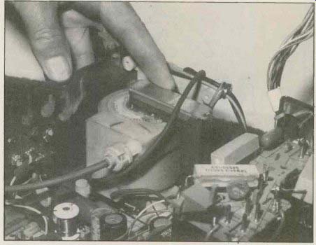
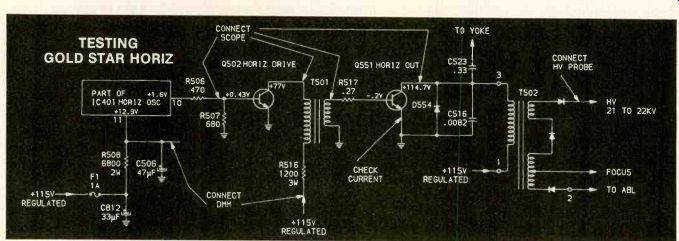
Figure 1. All three horizontal stages of the Gold Star CNR-405 (Photofact
1993-1) are supplied from the regulated + 115V supply that comes from rectification
of 60Hz line voltage plus transistor regulation. Therefore, testing can
be done on the oscillator and driver stages even when the output stage
is not operating. Some likely points to connect DMM, scope and HV probes
when troubleshooting this circuitry are marked by arrows.
Integrated flybacks in the later models might have internal arcing between windings and the high-voltage diodes. This arcing can be accompanied by loud popping and cracking noises. During power-on operation, watch the flyback carefully, looking for signs of smoke, bubbles in the plastic covering, or any arcovers between a winding and chassis. After a short time of operation, up-lug the machine and with caution feel the flyback, searching for hot spots or an abnormally warm body.
Flybacks are susceptible to being destroyed by any large overload, such as a shorted yoke and pin cushion wiring or serious leakages of one or more of the dc-voltage pulses that are rectified from flyback pulses. A flyback horizontal-output transformer can be destroyed by excessive high voltage produced by an open retrace-tuning capacitor (the largest capacitor in parallel with the damper diode), although the output transistor is even more likely to be shorted from those higher peak voltages. A leaky tripler rectifier or yoke might overload the flyback, tripping the circuit breaker (or blowing the fuse, whichever is provided) or causing a shutdown from excessive HV rectifier current.
Test equipment needed:
For finding defective flybacks, the absolute minimum includes a wideband ac/dc-coupled triggered oscilloscope, a dependable DMM with diode test: a do HV probe with meter, and a 60Hz transformer giving 0 to 130Vac output with isolation between in put and output. These two functions might be in two components, but the penalty is more clipping of the waveform tips than usual.
Minimize this clipping (and some problems with certain start-up circuits) by using larger-than-necessary transformers of higher wattage ratings.
Accurate voltage, resistance and current readings can be made by the DMM almost anywhere in the horizontal system. The scope can view waveforms from the horizontal oscillator to the horizontal-output transistor's collector during troubleshooting. And a high-voltage probe is required to find out whether the do high voltage is low, correct or high. If necessary, all three instruments can be connected to different points in an intermittent chassis. After the intermittent has occurred, the results from one or two of the readouts should show the approximate location of the problem. For example with low voltage, they can be connected with the DMM to the horizontal-oscillator B+, the scope to the output-transistor base and the probe to the CRT. Then the readings are watched and analyzed as the line voltage is in creased slowly from 30 Vac to 80 or 90 Vac, which should permit some operation when the circuit is not defective, while protecting the out put transistor and other sensitive components if the circuit still has defects. Remember, a shorted fly back or other serious load on the horizontal-output transistor usually destroys the transistor instantly. Practice and refine your technique for using the variable ac-voltage transformer to allow testing at lower voltages.
Other measurements
Unsolder the wire at the horizontal-output transistor's emitter and connect a dc-current meter between the wire and the emitter pin. The current reading should prove whether or not the horizontal circuits are overloaded.
Abnormally high current could indicate insufficient base drive or a heavy load on the collector of the output transistor.
In older color receivers, the out put transistor emitter current measured between 350mA and 600mA. These televisions had little load on the flyback except the high voltage. Present-day receivers re quire from 500mA to 1.5A of output-transistor emitter current, and the flybacks must supply additional power for several scan rectification low-voltage sources. In the RCA CTC120 chassis for example, there are nine different voltage sources, and the output transistor's emitter current is about 1.2A.
Practical troubleshooting
Horizontal-sweep systems with the horizontal-oscillator and driver stages powered from the low-voltage dc-power supply (instead of a supply produced by rectification of a flyback signal) are easier to troubleshoot for problems involving overloads of the horizontal-output transistor. The horizontal-output transistor can be removed and the oscillator and driver operated first at 120Vac line voltage, while the scope and DMM check those two stages for correct operation. (Figure 1.) If they are not operating correctly, the defects in them must be corrected before the output transistor is reinstalled and full power applied. If the two stages are operating correctly, the problems apparently involve the horizontal-output stage, which then must be tested at a low line voltage to pre vent ruining the output transistor or other components.
After a leaky or shorted horizontal-output transistor has been replaced, connect the current meter in series with the output transistor's emitter, and connect the HV probe to the HV connector on the picture tube (and to CRT ground, of course). The scope and DMM will be used for many different measurements, so they can not be connected permanently.
Finally, obtain ac power from the isolation/variable-voltage ac transformer. Begin with the DMM testing do voltage at the output transistor collector; adjust the scope for an expected waveform at the output-transistor's base.
Starting near zero, slowly in crease the receiver ac power until about + 60V is measured by the DMM at the output transistor's collector. Check the emitter cur rent meter. If the current reading is more or less than half the rated current, stop and make an evaluation. Much less current might indicate a lack of proper base wave form or an open in the flyback.
Much higher current than the half mark is the danger area. Perhaps the output transistor has leakage at the operating voltage. The flyback might have shorted turns or leakage to ground. Or the yoke or one of the scan-rectification power supplies (powered from the flyback) could have an excessive load. These possibilities should be investigated now at low-ac voltage before full line voltage is restored.
Scope the output transistor's base-drive waveform. A photograph shows the correct waveform of a similar receiver when operated with full line voltage. Of course, the amplitude will be lower and the waveshape will be less complex when the chassis is operated with a lower voltage during testing. Loss of base signal, an unrecognizable waveform or a very weak amplitude indicate problems in the horizontal-driver or oscillator stages. They must be tested separately (with output transistor removed and full line voltage) using DMM and scope.
While continuing to use the same line voltage that gave + 60V at the horizontal-output transistor, scope the collector waveform. If the waveform has ringing or insufficient amplitude (with or without a large pulse about midway be tween the correct ones), it is likely that the flyback, or one of its loads, has become defective and added a virtual ac short to the flyback. Erratic pulses might be caused by arcing of the internal high-voltage diodes inside the flyback. If the output collector waveform is normal (for the reduced test voltage) but the current is excessive, one by one remove the wires supporting scan-rectification do voltage supplies and other sweep-powered circuits.
Checking the yoke--To determine if the yoke is shorted and thus loading down the horizontal circuits, remove the red wire from the yoke terminal.
A large reduction of dc emitter current indicates the yoke has shorted turns: Replace the yoke.
Remember that each of many models (the Gold Star not included) has a yoke plug with a jumper wire between two pins. When the yoke plug is removed, the absent jumper wire removes the B + from the sweep circuits to prevent their operating without the yoke loads. That is not a hazard at the low voltages used for these specific tests.
Therefore, if disconnecting the yoke had little effect on the output's dc emitter current, suspect overloads from the flyback secondary winding circuits. First, check each rectifier, using the voltage-drop diode test of the digital-multimeter. In the event some tests are inconclusive, unsolder the anode of each diode, and if the correct emitter current is restored without any noise pulses in the collector's waveform, you have located the general source of the overload. Then troubleshoot the rectifier circuits for any defective diode, filter capacitor, bypass capacitor, resistor or zener diode that might cause high leakage and load-down the flyback.
----------24
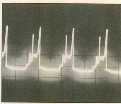
This is a typical waveform obtained at the horizontal-output transistor's base. Waveforms taken from other models will be slightly different.

Figure 2. A high collector voltage (+159V vs. +113V) in a Wards GGY-16210C
(Photofact 1961-3) usually indicates an open Q402 output transistor or
lack of drive signal to the base.

------- Figure 3. Instantaneous blowing of the F901 1A fuse was
the only symptom of the 9M50 Admiral (1667-1). At lower line voltages,
the fuse would blow when the horizontal-output transistor's collector dc
voltage reached + 75V. After many tests from the horizontal oscillator
to C709, nothing could be found defective, although 0750 and C709 were
replaced on speculation.
Therefore. T700 was replaced and normal operation was obtained.

---------- Replacing the defective T400 flyback in Wards GGY-16210C portable restored the high voltage and picture (Photofact 1961-3).
HV shutdown -- To determine when a chassis is shutdown from excessive high voltage, use the variable ac-voltage transformer again. Slowly increase the receiver's ac input voltage and notice the relationship between the rising ac and the in creasing low voltage and the HV. When the ac voltage is only 80Vac, but the low voltage is excessive, the LV regulator probably is at fault.
Check Q801, D806, R804 and other components around Q802 and Q801 (see Photofact 1993-1).
Monitor the high voltage and notice the lowest ac input voltage that activates the shutdown. If the low-voltage regulation is operating correctly, but the shutdown is activated before the line voltage is raised to 120Vac, the cause could be excessive high voltage or a defect in the safety shutdown circuit.
One fast way to test is to start at perhaps 80Vac and measure the high voltage as the ac input is in creased slowly. If the two voltages rise in step, and at 100Vac the HV is 10% to 15% below the normal value, then shutdown occurs when the ac reaches 100Vac, the problem definitely is in the safety shutdown circuit. On the other hand, if the two voltages are not in step, but at about 100Vac the high voltage has already reached the normal value, followed by an increase to above normal before shutdown occurs at perhaps 110Vac, the source of the problem is excessive high voltage. As stated before, retrace-tuning capacitor C516 is the first suspect (Figure 1).
Remember that the amount of B+ voltage applied to the horizontal-output transistor's collector directly affects the amount of high voltage. Always test the B+ supply and adjust its voltage, if necessary. If a method is provided, also test the shutdown operation after making repairs in the horizontal system.
Wards without picture or sound
In a Wards GGY-16210C port able television (Photofact 1838-1), the Q402 horizontal-output transistor's collector de voltage was high at + 159V (normal + 113V), indicating an open transistor or greatly insufficient drive signal at the base (Figure 2).
Previously, Q402 and damper diode SC448 had been replaced. I scoped the Q402 base pin, finding very little signal.
A normal waveform was scoped at the base of horizontal drive Q400. Next, Q400 was tested in circuit by using the junction voltage-drop measurement in my DMM. The forward-junction voltage and reverse leakage were satisfactory.
Q402 was removed and tested by the voltage-drop and leakage methods. While Q402 was out of its socket, I checked the base waveform with power on.
Although the waveform did not have the usual appearance, it was much higher in amplitude. Reasoning that Q402 might be breaking down under load or having some other defect that I couldn't test, I replaced it with an ECG165 universal. The results were unchanged.
Perhaps a defective flyback or yoke was loading the horizontal-output circuit. But if so, why didn't the CB500 circuit breaker trip open? The yoke's red lead was disconnected, but the results were the same.
Finally, the flyback was replaced and the problems were solved; the output transistor's collector voltage reduced to normal and the base drive was good. I drew a sketch of the flyback wiring connections, not only to help us wire this flyback correctly, but it was left with the schematic for possible use with future repairs.
Admiral blows fuses F901, the 1A fuse for the Q750 horizontal-output transistor in Figure 3, would blow as soon as it was replaced in the Admiral 9M50 TV chassis (Photofact 1667-1).
When the line voltage was raised from zero by the autoformer, the fuse would blow when the Q750 horizontal-output collector's do voltage reached + 75V. Q750 and retrace-tuning capacitor C709 have been known to fail in the past, so they were both replaced.
Unfortunately, the performance was no better.
When Q750 output was re moved, the 120V supply increased to + 132V when the line voltage was 120Vac. The Q750 base signal measured more than 6Vp-p. Q750 was replaced. The power line voltage was reduced to near zero and then slowly brought up to + 70V at the output transistor's collector (remember the fuse blows at + 75V). Next, yoke plug J751 was unplugged to eliminate any possibility of excessive loading from the yoke windings. Of course, pins 4 and 8 of the yoke socket were clipped together to supply do voltage to the pincushion circuits.
There was still no high voltage at the picture tube.
Replacement of T700 flyback with an original part number 79A195-1 solved the fuse blowing.
Another Admiral--The same F901 fuse would open in another Admiral 9M50 (Photofact 1667-1).
T700 was suspected of causing the fuse to blow because the symptoms were exactly the same: the fuse would open when the output transistor's de voltage was increased to + 85V. However, a few tests were made before T700 was replaced, because replacing a flyback is costly in time and material. Only + 17V was found at the + 24.5 source for the deflection module. A more important test was finding a shorted D700 (Figure 4) and the near-zero voltage at the + 41.2V source. It is hard to understand why the shorted D700 in the + 41.2V source (rectified horizontal sweep) could have much effect on the + 24.5V source that is bridge rectified 60Hz from a winding on a voltage-regulated power transformer.
Replacement of D700 restored the horizontal-deflection/high voltage operation and the television operation was normal.
Incidentally, remember that all diodes used to rectify horizontal-deflection signals or any signal of that frequency should be the fast-recovery type. Otherwise, the out put voltage might be lower than it should, and the diode could operate warmer.
Shutdown in Sharp
Immediate shutdown occurred in the Sharp KMC-1984 model (Photofact 1900-2) when ac power first was applied. At first , the receiver was suspected of overload shutdown from a defect in the flyback circuit. When the ac line voltage was increased slowly, shutdown occurred at 92Vac.
Therefore, we reduced the ac voltage to nearly zero and in creased again, but this time stop ping at 87V just short of shut down, where tests were made.
About + 82V was the highest supply voltage produced by turning up the + 120V adjustment (R709), but it proved the low-voltage de circuits were operating normally. At the horizontal-output transistor's base, the wave form measured approximately 14.2Vp-p. High voltage do at the CRT was 20.5kV (but 22.1kV or higher HV produced shutdown).
This does not compare favorably with the Photofact, which lists 25.5kV to 28kV at 120Vac without shutdown.

---------- Fig. 4.
This Admiral 9M50 also blew the same 1A fuse when power was applied, but the defect was not the same as the previous repair. Voltage tests revealed almost zero voltage at the + 41.2V source, and another test located a shorted D700.
Replacement of D700 and several adjustments completed that repair.
------------- SHARP SHUTDOWN PROBLEM
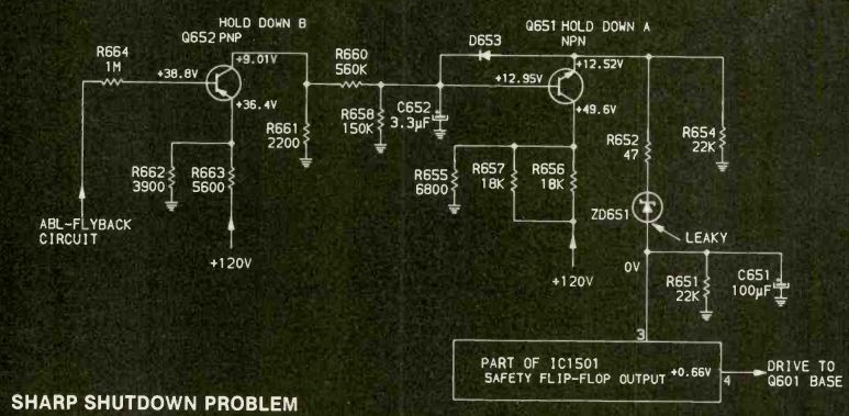
Figure 5. An overactive shutdown circuit was turning off the horizontal-sweep
circuit in a Sharp KMC1984 (Photofact 1900-2).
Using the variable low-line-voltage method, tests proved the high voltage was not excessive; therefore, the shutdown circuit must be the problem. It was. Replacement of zener diode ZD651 stopped the premature shutdown.
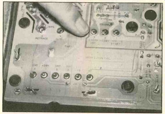
----------- Pins of the RCA CTC131 flyback transformer go through
eyelets in the circuit board, protruding slightly; next, they are soldered.
To remove the flyback, all excess solder must be removed from each pin
until all pins are free, then the flyback can be lifted from the board.
Excessive high voltage was not activating the shutdown and the brightness was not excessive, so the overload shutdown should not be operating. Therefore, the safety shutdown circuit itself must have a defect that caused it to trip prematurely. This assumption was verified by dis-connecting the cathode of zener diode ZD651.
Afterward, the line voltage could be increased to the usual 120Vac without any problems. Now there could be no doubt: The shutdown circuit had a defect.
Transistors Q651 and Q652 were tested in-circuit with the voltage-drop diode test and found to be good. Next, all diodes were tested in-circuit and none were found defective. However, zener ZD651 had been checked only in the for ward resistance direction. After some false trails had been followed, I checked the reverse resistance of ZD651 (which still was disconnected) and found the zener was very leaky, even when checked on a DMM (see Figure 5).
Installation of a new 18V ZD651 followed by several minor adjustments calmed the quick-triggering shutdown, producing excellent picture and sound from this Sharp television.
Miscellaneous suggestions When removing a flyback, first draw a sketch of the various wires that are connected to the terminals. If the wires are color coded, write the colors on the sketch beside each wire. After you finish, go back and check the colors again; some colors are difficult to distinguish until compared carefully. If you remove more than one wire from a terminal, tie the wires together temporarily; this will help identify them when it is time to solder them to the new trans former.
You do not have to worry about correct wires with the latest RCA chassis, such as the CTC131 shown in the photograph, because each flyback pin is soldered into a rivet or eyelet. To remove the flyback transformer, remove all possible solder using solder-wick or a vacuum device. Remember, all terminals must be free or the flyback cannot be removed. After the new flyback is installed, check each eyelet for good soldering. And sometimes the board wiring breaks at an eyelet (on the bottom of the board). Where possible, double check the continuity using the lowest multimeter resistance range from each eyelet to a component connected (according to the schematic) to the same transformer terminal. All soldered joints should have critical visual inspections on both sides of the board.
Remember, with remote controlled models, to bypass the on-off relay or supply 120Vac direct to the low-voltage power supply in those receivers that will be undergoing the variable-ac-input tests. If screen-and focus control components are supplied with a flyback kit, be sure to use them. Dress down the picture-tube heater windings to prevent future arcing and possible CRT damage.
And speaking about arcs, do not intentionally draw a high-voltage arc, either ac before rectification or dc. Some technicians have been known to create arcs and then try to estimate the amount of high voltage from the length, intensity and appearance of the arc (perhaps because they have no HV meters).
This practice is strongly condemned for solid-state receivers for several important reasons. It is dangerous for the technician and difficult to do because there are no convenient points for safely forcing an arc between the HV at the picture tube and ground, for example. The manufacturers have ex pended much time and money to make certain arcs cannot occur.
The HV wire is covered from the flyback to the CRT with no connectors in between.
However, there is another reason you should not draw arcs: Arcs can ruin solid-state components.
Arcs produce steep-sided (fast-rise-time) waveforms in the HV do voltage, and these pulses are directly applied to the HV-rectifier diodes that usually are inside the newer flybacks. Also by trans former action, these pulses (perhaps with lower amplitude and changed waveforms) are applied to the damper diode and the horizontal-output transistor's collector. These conditions are likely to cause damage, but the reason will not be apparent unless you understand that the amplitude of arcs can be increased by the fixed-tuned circuits (both intended and accidental) that are present in the flyback primary and secondaries.
One of my worries is that many technicians are not taking seriously the advice to use an isolation transformer on the TV receiver when test equipment is to be connected to it. But it is a real danger to you, the test equipment and the television. Most late-model color receivers each have a low-voltage power supply that is rectified by one or four diodes from the 120Vac line. Therefore, the chassis ground might have a voltage (measured to a good earth ground) any where between zero and more than 100V peak. As many of us have found, connecting the ground of a 3-prong-ac-plug oscilloscope to that so-called cold ground often shorts one or more bridge diodes, blows open a safety surge resistor and blows a fuse. Power of this magnitude certainly would pro duce a severe shock (or worse) in a technician.
Fortunately, the solution is simple: just use an isolation trans former to supply 120Vac for the receiver. Then add a variable-ac voltage transformer (either with its own isolation transformer or in addition to it) and you will find a new ability to test safely for shorted flybacks and other massive shorts without zapping a series of replacement horizontal-output transistors. During those procedures, the receiver's ac power voltage should be reduced to whatever is needed according to the symptoms and the specific defect. Several examples have been given in this article.
= = = =