Described by Roger Harrison, VK2ZTB
CRYSTAL OSCILLATORS, in one form or another, are fundamentally associated with virtually all transmitting and receiving equipment. Basic circuitry and circuit techniques, and the fundamentals of quartz crystals are discussed at various length by both the AR R L and RSGB handbooks, Pat Hawker's 'Amateur Radio Techniques', the various VHF handbooks by Jessop ( RSGB) and Tilton ( AR R L) as well as 'The Radio Handbook' by Bill Orr ( Editors and Engineers). A useful, and more recent discussion on the subject of crystals and crystal oscillators is contained in the ' Ham Notebook' from the editors of the American journal ' Ham Radio'. For a deeper appreciation of the subject, references (1) to (4) are recommended.
Basic solid state crystal oscillator circuit techniques are by now well established, most circuits being adaptations of the well-known vacuum tube technology such as the Pierce, Hartley, Clapp and Butler oscillator and use both bipolar and FET devices.
Whilst these circuits basically fulfill their intended purpose, there are many applications which require something different or where performance needs to be reliably characterized.
Presented here are a variety of circuits, for a range of applications from LF through the VHF range, that are not commonly found in current amateur use or literature.
MODES OF OPERATION
A point not often appreciated, or just forgotten, is that quartz crystals can oscillate in a parallel resonant mode and a series resonant mode. The two frequencies are separated by a small amount, typically 2-15 kHz over the frequency range. The series resonant frequency is lower in frequency than the parallel. A crystal specified and calibrated for use in the parallel mode may be satisfactorily used in a series resonant circuit if a capacitor equal in value to its specified load capacitance ( usually 20,30, 50 or 100 pF) is connected in series with the crystal. Sadly, you can't invert the process for series resonant crystal in parallel mode circuits. The series mode crystal will oscillate higher than its calibrated frequency in this case and it may not be possible to capacitively load it down sufficiently.
Overtone crystals operate in the series mode usually on the third, fifth or seventh overtone, and the manufacturer normally calibrates the crystal at the overtone frequency.
Operating a crystal in the parallel mode and multiplying the frequency three or five times produces quite a different result from operating the same crystal in the series mode on its third or fifth overtone. When ordering overtone crystals avoid confusion and specify the frequency you want, not the apparent fundamental frequency.
Reference (4) makes this point quite clear.
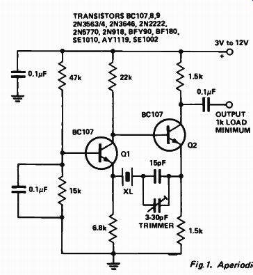
Fig. 1. Aperiodic Butler oscillator (series model
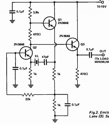
Fig. 2. Emitter-coupled oscillator - after Lane (3). Series mode.
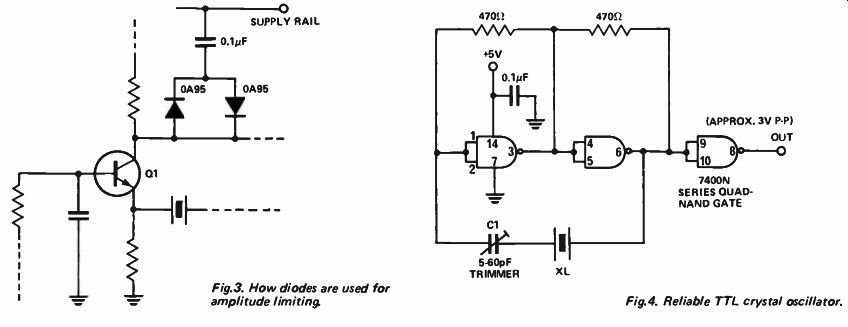
Fig. 3. How diodes are used for amplitude limiting.
Fig. 4. Reliable TTL crystal oscillator.
Fundamental crystals in the range 500 kHz to 20 MHz are usually specified for parallel mode operation but series mode operation can be requested. For low frequency crystals, up to 1 MHz, either mode can be specified. Overtone crystals generally cover the range 15 MHz to 150 MHz.
WIDE RANGE or A PERIODIC OSCILLATORS
Oscillators that do not employ tuned circuits can be very useful, whether they are simply used as 'crystal checkers' or some other purpose.
Particularly for LF crystals, tuned circuits can be bulky. However, they aren't without their traps. Some crystals are prone to oscillation on unwanted modes, particularly the DT and CT cut crystals used for LF quartz oscillators. It is wise to check that the output is on the correct frequency and no mode instability is evident.
Reducing feedback at the higher frequencies usually cures this. In extreme cases, the idea has to be abandoned and an oscillator having a tuned circuit used instead, ( LF crystal oscillators are discussed later). The first circuit is an emitter-coupled oscillator, a version of the Butler circuit. The basic circuit first appeared in VHF Communications in 1970 (p.240) as portion of a VHF-UHF calibration spectrum generator.
Versions have subsequently been published in the ' VK5 Bulletin' ( S.A. Div. WIA) in 1972 and 6UP, August issue, 1974. Lane (3) discusses a variation of this circuit ( Fig. 2). The output of the circuit in Fig. 1 is essentially sine wave; reducing the emitter resistor of 02 increases the harmonic output. By doing this, a 100 kHz crystal produces good harmonics through 30 MHz. It is a series mode circuit.
A variety of transistors may be used.
For crystals above 3 MHz, transistors with a high gain- bandwidth product are recommended. For crystals in the 50 kHz to 500 kHz range, transistors with high LF gain, such as the 2N3565 are recommended. Also, for crystals in this range, permissible dissipation is usually less than 100 microwatts and amplitude limiting may be necessary.
Low supply voltage, consistent with reliable starting, is recommended.
Modifying the circuit by the addition of diodes -- as shown in Fig. 3 -- is a better method, and starting performance is improved. The circuit will oscillate up to at least 10 MHz with appropriate transistors and emitter resistor values. An emitter follower or source follower buffer is recommended. Similar comments to the above apply to Fig. 2. An emitter follower buffer is included in this circuit. Both circuits are slightly frequency sensitive to power supply voltage changes and load variations. A load of 1 k or greater is recommended.
TTL IC can be used in crystal oscillator circuits but many published circuits have poor starting performance or suffer from non- repeatability owing to wide parameter spreads in IC's. The circuit in Fig. 4. is by K1PLP from QST, Feb. 1974 ( 5) and is after Weggeman ( 6). This circuit has been tried by the writer over the range 1 MHz to 18 MHz and can be recommended. It is a series mode oscillator and suits AT-cut crystals. The output is about 3 volts peak to peak, square wave up to about 5 MHz beyond which it is becomes more like half-sine pulses. Starting performance is excellent, often a critical factor with TTL oscillators.
LOW FREQUENCY CRYSTAL OSCILLATORS
Crystals in the range 50 kHz to 500 kHz require special considerations not encountered with the more common AT or BT cut HF crystals. The equivalent series resistance ( which determines 'activity' - that figure of merit of days of old) is much greater and their permissible dissipation is limited to less than 100 microwatts, preferably 50 microwatts or less.
The circuit in Fig. 5. is a series mode oscillator described by Lane ( 3). It has the advantage of ot requiring a tuned circuit, and has a choice of sine or square wave output. For crystals in the range 50-150 kHz, 2N3565 transistors are recommended although the author has found BC107's satisfactory. Either type will suffice for crystals in the range 150 kHz to 500 kHz. If you find the crystal will not start reliably, most likely the crystal has a very high equivalent series resistance, in which case increase R1 to 270 ohms and R2 to 3.3 k ( as recommended by Lane). For square wave operation, C1 is 1 uF (or a value close to, or above it). For sine wave output, C1 is not in circuit.
Amplitude limiting is unnecessary.
Sine wave output is about 1 V rms, square wave output about 4 V peak to peak.
+
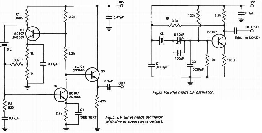
Fig. 5. LF series mode oscillator with sine or squarewave output.
Fig. 6. Parallel mode LF oscillator.
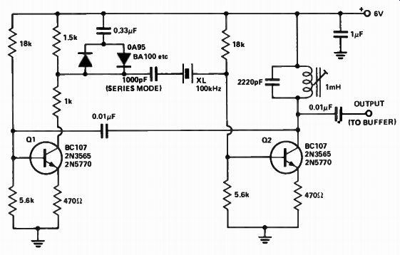
Fig. 7. 100 kHz crystal oscillator (with tuned circuit).
The circuit in Fig. 6 is also described by Lane ( 3) and can be recognized as a modified form of the Colpitts oscillator, with the addition of resistor Rf to control feedback ( it works the same way as Eno's). Capacitors C1 and C2 should be reduced by preferred values as the frequency is increased. At 500 kHz, values for C1 and C2 should be around 100 pF and 1500 pF respectively.
The circuit as shown gives sine wave output with the second harmonic about 40 dB down ( or greater). This can be reduced by careful trimming of Rf and Cl. Note that, at the reduced level of feedback necessary to achieve this, it takes some 20 seconds for the oscillator to reach full output. Output is about 2 to 3 volts peak to peak.
If you need an output rich in harmonics, the simple addition of a 0.1 uF capacitor across the emitter resistor will achieve this. Output then rises to about 5 V peak to peak. Power supply voltage can be reduced in this case to lower crystal dissipation.
Other transistors can be used, but bias and feedback may have to be adjusted. For cantankerous crystals determined to oscillate in modes other than those you wish, the circuit of Fig.7 is recommended. Feedback is controlled by tapping down the collector load of 01. Amplitude limiting is necessary to keep the crystal dissipation within limits. For 50 kHz crystals the coil should be 2 mH and its resonating capacitor 0.01 uF. Output is about 0.5 V rms, essentially sine wave. The use of an emitter follower or source follower buffer is recommended. If a parallel mode crystal is used the 1000 pF capacitor shown in series with the crystal should be changed to the crystal's specified load capacitance (usually 30, 50 to 100 pF for these crystals).
HF CRYSTAL OSCILLATOR CIRCUITS
Solid state circuits for the popular AT-cut HF crystals are legion.
However, results aren't always what one would expect. Most fundamental crystals up to 20 MHz are , usually specified for parallel mode operation.
However, such crystals can be used in series mode oscillators by putting the specified load capacitance in series with the crystal as mentioned previously. Both types of circuit are detailed here.
A useful oscillator for the range 3 to 10 MHz that does not require a tuned circuit is given in Fig. 8 ( a). It is, of course, the same circuit as Fig.6. The circuit can be used down to 1 MHz if C1 and C2 are increased to 470 pF and 820 pF respectively. It can be used up to 15 MHz if C1 and C2 are reduced to 120 pF and 330 pF. Respectively. This circuit is recommended for non-critical applications where high harmonic output is wanted, or not a consideration.
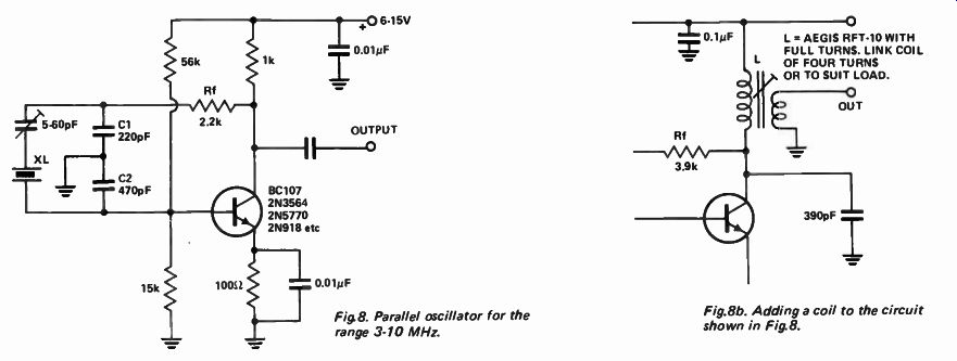
Fig 8. Parallel oscillator for the range 3-10 MHz.
Fig.8b. Adding a coil to the circuit shown in Fig. 8.
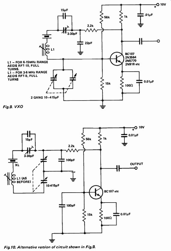
Fig.9. VXO
Fig. 10. Alternative version of circuit shown in Fig.9.
The addition of a tuned circuit as in 8 ( b) reduces harmonic output considerably. A tuned circuit with as high a Q as possible is recommended.
In a 6 MHz oscillator, I have obtained the following results. With a coil Q of 50 the 2nd harmonic was 35 dB down.
With a Q of 160, it was -50 dB! Resistor Rf can be adjusted ( increase slightly) to improve this. The output is also increased with a high Q coil. As previously noted, with reduced feedback it takes some tens of seconds to each full output from switch on, however, frequency stability is excellent.
Operation at other frequencies is accomplished by changing the capacitors and coil appropriately.
This circuit ( Fig. 8) can also be turned into a very effective VXO. A small inductance is placed in series with the crystal and one of the capacitors in the feedback circuit is made variable. An ordinary two-gang 10-415 pF (or thereabouts) broadcast tuning capacitor will do the job nicely.
Both gangs are paralleled. The tuning range depends on the crystal used, the inductance of L1 and the frequency. A greater range is usually obtainable with the higher frequency crystals. Stability is excellent, approaching that of the crystal.
Another variation of this circuit is shown in Fig. 10. This circuit may allow more 'pull' on the crystal, but stability is poorer. For both Fig's 9 and 10 the trimmer is to set the nominal frequency at some position of the tuning capacitor. For both circuits also, especially for Fig.10, the output varies across the tuning range.
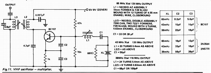
Fig. 11. VHF oscillator - multiplier.
A VHF OSCILLATOR-MULTIPLIER
The circuit in Fig.11 is a modification of the ' Impedance Inverting' overtone oscillator discussed by Rankin (4), who also describes a similar circuit ( albeit outdated - using an 0C171 - even Dick Smith no longer stocks them!) Normally, with the impedance inverting circuit, the collector is either untuned or grounded for RF. The collector can be tuned to twice or three times the crystal frequency To reduce the output at the crystal frequency, a double tuned circuit is recommended.
DO NOT tune the collector to the crystal frequency, otherwise the circuit will oscillate at a frequency not controlled by the crystal. It is advisable to keep the collector lead as short and direct as possible.
Results with this circuit are excellent. All outputs other than the wanted output were at -60 dB or greater. Noise output is at least 70 dB below the wanted output. It makes an excellent conversion oscillator for VHF/UHF converters. Almost 2 V of RF is available at the hot end of L3 (author's prototype at 30 MHz). A Zener regulated supply is recommended. As indicated on the diagram, different circuit values are necessary for different transistors.
Strays in individual construction may also necessitate variations. L1 can be used to pull the crystal onto frequency.
Slight variations in frequency ( about 1 ppm) occur when tuning L2 and L3 and also with load variations.
However, in practice, these turn out to be of no consequence.
REFERENCES
(1) 'Radio Transmitters', L. Gray & R. Graham ( McGraw-Hill)
(2) 'Electronic Fundamentals & Applications', J. D. Ryder (Pitman)
(3) 'Transistor Crystal Oscillators to Cover Frequency Range from 1 kHz to 100 MHz' by M. Lane, Australian Post Office Research Laboratories, Report No. 6513.
(4) 'Overtone Operation of Quartz Crystals' D. Rankin ( VK3QV), Amateur Radio, March and May 1967.
(5) 'A TT L Crystal Oscillator', K 1P LP, QST February 1974, p.34.
(6) ' IC-Compatible Crystal Oscillator', The Electronic Engineer, May 1969.