In his third article, the author discusses the transfer of electronic signals (digital data) within the MPU chip itself. The concepts behind locating, storing, and manipulating of the data are explained and illustrated.
By Bernard B. Daien
The previous article covered "talking to the MPU"... the various "languages" we can use for inputting data and instructions, and the reasons why we use them. Logically then, we should ask, "What happens next? What does the MPU do with the information in the language used?" This article endeavors to provide that next step-in continuity.
We mentioned in Part II that some MPUs operate with a four bit byte ... most of the current MPUs use an eight bit byte, and some of the newest machines are going to a 16 bit byte. A four bit byte has only 16 possible combinations, an eight bit byte has 256 combinations, and the 16 bit byte has 65,536 combinations! It is obvious that an eight bit byte machine can handle more information, and is capable of handling a larger memory, than a 4 bit byte machine.
Since a byte is generally also a "word," a given program can be achieved more easily on the 8 bit machine because fewer words are needed. The trend is therefore toward MPUs with longer bytes...but there are some disadvantages in the use of longer words...
Serial versus parallel
Depending upon the originating source, information may be either "serial" or "parallel" form. The word serial means that the information is delivered one bit at a time, the way sentences are formed using a typewriter. Each letter follows the previous one in time, and you must wait for each word to be completed.
Parallel indicates that all eight bits of a word are delivered simultaneously, the way a rubber stamp imprints all the letters at the same instant in time.
Obviously, an eight bit word would take longer to deliver than a four bit word, in serial format, thus slowing the operation of the MPU system.
In order to avoid this slowdown, MPUs are designed to operate with parallel format, since it takes only one operation to handle all 8 bits of a word. This implies that all the internal operations of the MPU are done on eight parallel wire connections called "buses." Some buses handle data (data bus), others handle memory locations, (these are often two 8 bit buses, or a 16 bit bus, to handle the larger number of addresses which may exist in external add-on memory). These will be covered in greater detail later in the series. For now, we need only know that computers are generally rated in "computing power," which is the ability to handle information per unit of time. The faster a machine is, the more "powerful" it is said to be ... a figure of merit in comparing computers.
Some of the larger machines are so fast, that many customers share them, thus increasing profitability.
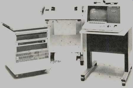
Fig. 1 Representative of the avalanche of microprocessor controlled devices
now invading every segment of electronics from industrial to consumer applications
is this Model 64000 Logic Development System from Hewlett-Packard. With such
devices design engineers and programmers are able to move more rapidly from
project definition to production all of the microprocessor based products which
they design. This unit is used in design, debugging, and troubleshooting situations.
Some information sources generate serial formats, and this necessitates the use of an interface device which is able to accept information in serial form, storing it bit by bit until an entire word is completed, and then delivering the entire word, in parallel format, to the MPU. Obviously this requires some form of memory...which brings us to the point where we must mention memories. However, we will discuss them in depth later.
Registers and latches Different names are applied to memory devices which provide temporary, short term storage of information. The name may be dependent upon the use the device is put to, rather than upon the device itself. Often this leads to confusion. In general, we say that any device capable of storing binary information is a "memory"...whether it be magnetic tape, magnetic disc, or an integrated circuit. For now we will talk about integrated circuits only.
If such a device is used for short term storage, as, for example, during the short time interval needed to transfer data from one part of the MPU to another, it is called a "register." The registers in an MPU are organized to handle one or more 8 bit bytes, so that information moves about in word length chunks. (There are some memory devices that handle only one bit, and these are called "latches." A latch is nothing more than a flip-flop, a bistable multivibrator, which can be set in either a 1 or a zero state, and will hold that state until reset.) If you think about it, a register is really nothing more than eight latches in one device, each latch handling one bit, with some common control terminals to facilitate handling all 8 bits simultaneously. If we use a register which can handle 8 parallel lines (one for each latch), we can interface any device, serial or parallel, with the MPU.
There are a variety of specialized interface devices available, each better suited for the many different interfaces required, all with the capability of providing parallel input to the MPU. For example, we may wish to accept information from a teletype machine, or from a telephone line, or from another computer...these are illustrations of what we meant in the first part of this series when we referred to the need for interface devices. (Often interface devices are referred to as "Input/Output'' devices, or simply I/O devices, since they are part of the family of I/O.)
The "clock"
Since serial information is delivered at a slower rate than parallel information, the element of time is involved. In a general sense then, an interface device often provides the capability of connecting together two different circuits running at different speeds. (When two circuits run at the same speed, locked together, they are said to be "synchronous." If they run at different rates they are "asynchronous.") System speed rate is determined by an oscillator (pulse generator), called a "clock." The clock is generally frequency controlled by a quartz crystal for stability...the circuit is usually a crystal controlled multivibrator.
Often two outputs are taken from the clock, 180 degrees out pf phase, in which case it is said that we have a "two phase clock."
One device frequently used to interface systems running at different clock rates is the "Asynchronous Communications Interface Adapter" or, simply ACIA. This very useful little integrated circuit converts serial information to parallel, parallel information to serial, and is capable of doing this on circuits with different clock speeds! Since incoming data from telephone lines, teletypes, etc., is serial, the ACIA enables these devices to talk to the MPU, which demands parallel format.
On the other hand the ACIA is also able to convert the parallel output of the MPU into the serial format required for transmission over the telephone lines.
Thus the ACIA is a versatile, complex, I/O interface device, necessary for use with the MPU in a great many applications. There are many other specialized interface chips available for other uses ... but one example will suffice for the purposes of this series, at the moment.
Control instructions
Now that we know what a clock is, what a register is, and what a bus is (among other terms just discussed) ... we can proceed to put the pieces together in order to obtain an overall view of what the MPU does with the information we input to it.
In order to do this we will take a step backwards and ask a question. "How does the MPU know what to do when we give it an instruction?" Well, how does a child know what to do when we say "It's time to eat." Or, "Go to bed." Of course a child is not born with this knowledge ... someone had to teach it...to implant in the child's memory the procedures to be followed when the child recognizes that phrase. So it is with the MPU. The MPU has a limited amount of memory right inside the MPU chip, and this memory is permanently programmed during manufacture with the ability to initiate certain operations upon command. The control process is as follows.
Encoding and decoding
Upon receiving an instruction from the program, the MPU looks up that instruction in its internal memory, and discovers it is an order to perform certain operations. This look -up process, and translation into orders for operations is called "decoding." The operations which have been ordered from the memory built into the MPU are based on microinstructions. Microinstructions are the instructions which we just discussed, those which were built into the MPU at the time of manufacture. There are about 70 of these basic instructions in the vocabulary of most current MPUs, and they are called "the instruction set" for the particular MPU, because, in fact, they are a set of basic instructions. By combining instructions, we can make the MPU do many different things.
To differentiate between the instructions which are part of the MPU (built in), and the instructions in the program, program instructions are called "macroinstructions." (Micro means small, macro means large.) Thus the microinstructions are for the many small basic operations the MPU must perform to accomplish any task...for example, the moving of information from one part of the MPU to another internal part of the MPU via an internal bus.
When we tell the MPU to accomplish this, by means of a macro-instruction...which indicates, "Place the following data in Register A" (there are several registers in an MPU) ... of course the data must first be placed on a bus, then the bus must transfer the data to Register A, then the bus must stop transferring data so that unwanted data is not also jammed into Register A.
It is the microinstructions which indicate, step by step, the transfer of data onto the bus, and off the bus, in order to carry out the order of the macroinstruction. The macroinstruction does not spell out all these little details...and indeed it is not desirable for it to do so, otherwise we should be repeating all these little microinstructions in every macroinstruction, making programming an extremely long, tedious process.
A closer look
Let's look at these events even more closely. How does the MPU know exactly when it can put information on the bus, take it off the bus, or even just plain stop because the operations indicated in the microinstructions have been completed? Well, the clock plays a role in this. Information moves in little jumps, rather than a steady stream. If we are using a 1 MHz clock, there will be a million pulses a second from the clock, and each pulse can initiate some form of action in the MPU, therefore things will jog along at a million operations per second, or less. (Some operations take several clock pulses to complete.) The MPU will have to wait for a clock pulse before anything at all can move...and if it has to wait several clock pulses for a more complex operation to complete, the data may have to be temporarily put into one of the registers so that it is not lost while waiting. The microinstructions tell the MPU all it needs to know, in order to do this, and relieve the programmer of much tedious work. It's like baby training. Once the baby is trained to the point where it can speak, the tough part is over.
As a matter of fact, the programmer, using machine code, (usually hexadecimal) is merely inputting a number from zero to 255 (remember an eight bit word has 256 possible combinations), and that number is the "address" (location), in the MPU's internal memory, which contains the instructions for the operations to be performed. The MPU looks up that address, and performs the instruction located at that address (decoding). The hex number put in by the programmer is part of the MPUs instruction set. Got it now?
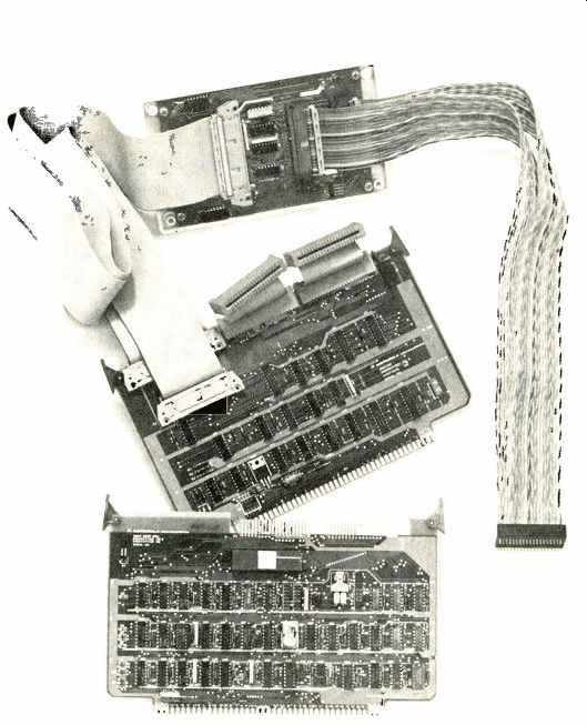
Fig. 2 Add on memory and logic boards, such as these from Motorola Microsystems,
Permit Expansion of existing hardware systems. In addition to providing users
with expanded memory (RAM) locations such "plug in" boards also permit
users to increase functional capabilities.
Add on memory
By using a series of program instructions (macroinstructions), in the proper combination, we can input data, instructions on what to do with the data, etc. ... in short, "programming." But what if we want to do things that are not in the "microinstructions" built in at time of manufacture? In that even we can add on extra memory, with more information.
At this time we should mention that microinstructions are held in "read-only" memory (ROM) and that means exactly what it says. We can read information out of the memory, but we cannot alter, add to, nor erase the memory. It is just like a book, although we use it, we do not change its contents in the process.
External add on memory can also be read-only if we wish it to be permanent, like the microinstructions. On the other hand there are times when we may wish a memory that can be altered, or even erased and reused...and such memories are known as "read-write" memories because we can not only read out of them, but we can also write new information into them. (Another common name for read-write memory is "random access" memory (RAM).
To make sure that you are getting a clear understanding of these basic MPU operations, we will look at a simple example. Suppose you wish to add two numbers together. You will have to provide the necessary data, and instructions, in a program, written in a language the MPU can understand. We are going to add the numbers 5, and 10.
(Data.) We must also include the word "Add" (Instruction). We will also need to make sure that the computer has been cleared of any previous data and instructions which it may still have in its various sections, (Initializing). You do this with a pocket calculator when you press the "Clear" button before starting a new calculation, remember? And you will have to make sure that the machine stops calculating at the end, so you need to input that information too.
Step by step
The MPU will put the first data entry, 5, into a register, to store it temporarily, while it goes on to your next data entry, 10, which is also stored in another register, while it goes on to look at the instruction, "add." Add is a microinstruction which, decoded, says that the two data numbers will be added together, and the result is then stored in another register until it is called for, or erased from memory. (Of course each of these instructions required routing information on the bus to the proper register, etc., but that was understood because it was part of the microinstruction previously discussed.)
The macroinstruction often calls out which register we want data held in, but the process of getting the signals into that register is determined by the microinstructions. It's like traveling on a superhighway. You may decide the destination, but the road has already been laid out, so that you merely follow the road instruction signs (microinstructions) through the various interchange loops, until you come to the proper exit. You do not have to mark your road map (programming) with each interchange, because it already has been done for you. That makes finding your way on a superhighway much easier than trying to get to the same place on the state or local highway systems.
The sequence
The MPU will take your instructions in the order in which you number them, and it does this automatically. When it completes one step in the program, it goes on to the next step, and this too is the result of microinstructions! So you see, the MPU needs, and uses, both microinstructions, and program instructions (macroinstructions). An important part of this process involves the temporary storage of information and, as a result of this need, modern MPUs have a dozen or more registers, with various titles, such as, "accumulator," "stack," "index register," etc., depending upon the use to which the register is put. This is very confusing to the student trying to comprehend what goes on inside the MPU, because the same thing may have a different name, when it performs a different function! (Part IV of this series will be devoted to clarifying that situation.)
Summary
This article covered serial and parallel formats, and explained the need for buses, and memories. Synchronous and asynchronous operations were defined, as was the term "clock." Interface adapters were covered.
Micro and macro instructions were delineated. Some of the movements of information inside the MPU were traced. The foundation for further coverage of the internal workings of the MPU was laid.
(source: Electronic Technician/Dealer, Jan. 1980)