|
|
(source: Electronic Technician/Dealer, Jan. 1980)
By Homer L. Davidson
Proper operation of the low voltage power supply and low voltage regulators is basic to many units of entertainment electronics. The technician must avoid being sidetracked into other areas of circuitry when the power supply is at fault.
Sometimes it's easy to overlook low voltage regulator circuits and spend useless hours in other circuits. The dead or intermittent TV chassis' trouble may be caused by the voltage regulator circuits in the power supply. Other symptoms caused by low voltage in the power supply may be insufficient width, poor sound, poor sync or no color.
The purpose of the low voltage regulated power supply is to stabilize the voltage applied to critical circuits. If the power line voltage changes from 115 to 132 volts, its regulated output voltage will remain constant, providing protection to the TV or radio circuits. In most TV circuits, with some type of voltage regulation, the dc output voltage is set at a certain voltage for correct circuit function. When the dc output voltage varies only 3 or 5 volts, the HV applied to the CRT may change several kilovolts.
The low voltage regulator circuit may be used in TV, radio or stereo chassis.
You may find in the TV chassis, a separate voltage regulator for critical stages. While in the stereo chassis, the whole B+ source may be regulated. A single zener diode may provide voltage regulation in the radio. Here we will show you how to service defective voltage regulator systems.
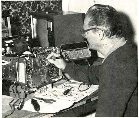
Fig. 1--Here a TV technician is servicing the voltage regulator circuit
of a portable color TV.
A simple regulator circuit
The simple voltage regulator circuit may consist of a zener diode or a couple of transistors (Fig. 2). In this circuit only one APF transistor is used for a regulated 12 volt source. The output voltage is varied with VR-3. Any voltage change from the power supply will be absorbed by the transistor circuitry.
You may find the simple voltage regulator circuit in a separate section of the TV chassis to supply the tuner and IF sections. The entire B source of a stereo compact may be controlled by a simple regulator circuit, while the auto stereo 8-track player motor supply may be regulated by a very simple zener diode circuit. Generally, the simple voltage regulator circuit is easy to service, but in some TV chassis you may find rather complicated circuits.
A deluxe regulator circuit
Here in a Panasonic portable color ETA-3 chassis, we find a more complicated voltage regulator circuit Background and case histories with 5 transistors, a thyristor and several diodes. This same chassis may be found under J.C. Penney and other TV labels.
This voltage regulator circuit can be serviced with a VTVM and scope (Fig. 3).
The full -wave rectifier waveform is applied to the base of TR801. TR801 is a pulse amplifier and sawtooth generator.
The output pulse from the collector of TR801 is converted into a sawtooth waveform by R806, R808 and C807 and is fed to the base of TR802.
Changes in the emitter voltage of TR802 results in a changing phase of the pulse at the collector terminal of TR802. Here, we find a square waveform. This squarewave voltage is differentiated by C808 and R811.
The collector of TR804 is connected to the emitter of TR802 through R813 (560). TR804 is a detector to compare the output voltage with a zener diode in the emitter circuit. Adjustment of R816 (500) in the base circuit of TR804 will adjust for an operating voltage of 115 volts at the load.
C808 (.01) couples the differentiated waveform to the base of the pulse amplifier TR803. The sharp positive pulse from the collector of TR803 is fed to the primary winding of transformer T801. The secondary winding of T801 is connected between the gate and cathode of thyristor TR805. If a parabolic waveform is applied to the anode of the thyristor and the voltage is lower than the cathode-gate voltage, no current flows into the thyristor gate and the thyristor ceased to conduct. Thus, TR805 keeps a constant voltage applied to the large filter capacitor C853 and the active power filter (APF) circuits.
The ripple voltage across capacitor C853 is undesirable and must be filtered. The active power filter (APF) circuit transistors TR806 and TR851 are employed to eliminate ripple. This filtering prevents the TV picture from fluttering due to an abrupt change of the ac line voltage.
Although this voltage regulator circuit may be a little more difficult to repair, it does a great job regulating the dc voltage source.
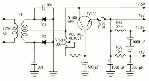
Fig. 2--A simple voltage regulator circuit may contain only one transistor
and a few components.
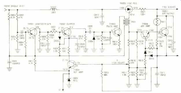
Fig. 3--A more complicated voltage regulator circuit may contain several
transistors, diodes and other components.

Fig. 4--You may find the voltage regulator circuitry packed or tacked
in any place in a Japanese TV receiver. Some of them may be a little
difficult to get at for servicing.
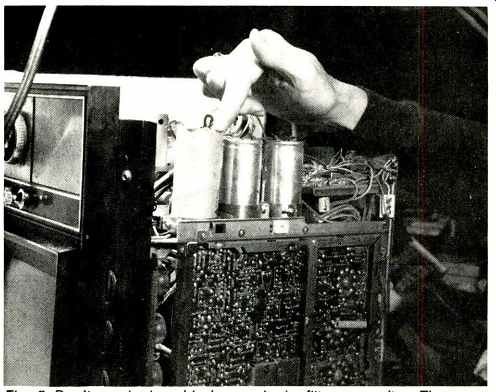
Fig. 5--Don't overlook a dried-up or leaky filter capacitor. These capacitors
range from 220 to 1500 mfd.
General troubleshooting
In a TV chassis, the symptoms caused by the low voltage regulated power supply may be insufficient width, intermittent raster or a completely dead set (Fig. 4). A defective regulator circuit in a stereo chassis may cause weak or no FM or AM reception. When the voltage regulator circuit in a car stereo 8-track chassis is defective, you may encounter fast or slow motor speed or a dead unit.
First, determine if the problem lies in the power supply or another circuit.
Measure the regulated dc output voltage. If the voltage is normal within 5 volts, suspect trouble in other circuits.
When the voltage is very low or cannot be varied with the voltage adjustment control, suspect problems in the power supply. To make sure, disconnect the low voltage source from the other circuits. Normally, you will see an increase of less than 5 volts at the output.
We must remember the failure of a voltage regulator transistor may be caused by an overload caused by other circuits. Be sure and check the horizontal output transistor and damper diode for leakage. Measure the resistance between the collector terminal of the horizontal output transistor and chassis. If the resistance is below 1K, remove the output transistor and check it out of the circuit.
While the transistor is out of the circuit, check the damper diode for leakage.
A dead chassis may be caused by a blown line fuse or silicon rectifier diode.
Check for dc voltage at the cathode terminals of the diodes or bridge rectifiers. If there is no voltage, check for applied ac voltage at the diode anode.
No voltage at this point may be caused by an open fuse, fusible resistor or defective off/on switch. An open power transistor in the low voltage regulator circuit may produce a dead set.
Improper voltage applied to the APF power filter transistors may cause low output voltage. Burned or changed tolerance of resistors produces improper voltage. Generally, open or leaky regulator transistors cause low output voltage. Don't overlook the main filter capacitor for low output voltage. A leaky zener diode may produce insufficient voltage to the various circuits.
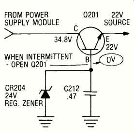
Fig. 6--An intermittent raster in a Zenith color TV chassis 23HC45 was
caused by a voltage regulator transistor opening up.
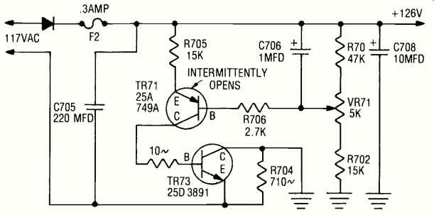
Fig. 7-Intermittent width problems are more difficult to locate. In
this Penneys' model 1022, TR71 would open up causing a low dc voltage.
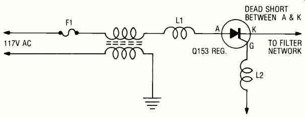
Fig. 8--A shorted thyristor in a Sears 528-42022506 chassis caused the
fuse to blow immediately, each time it was replaced.

Fig. 9--Output only a few volts low in this Monteverdi model CG-001-0014
caused weak FM and choppy AM reception.
No sound-no raster
When the solid-state TV chassis appears dead, measure the voltage at the low voltage source output or at the collector of the horizontal output transistor. Generally, the case of the horizontal output transistor is the collector and is easily located. If the voltage is normal at the horizontal output transistor, you may assume the trouble lies in the horizontal circuit. When the dc voltage is low at the horizontal output transistor, the problem may be caused by it or by the low voltage power supply.
Measure the low voltage supply at the source. If it is low, remove the horizontal output transistor to determine if the horizontal circuits are loading it down.
Generally, only a couple of chassis screws need to be removed to pull the suspected transistor. You may find the horizontal and audio output transistors operate directly from the highest low voltage source. If the dc voltage source returns to a little higher than normal with the horizontal output transistor removed, the trouble is in the horizontal circuit.
In case the dc output voltage is still too low or is absent, suspect a defective low voltage power supply. If no voltage is found at the output point, go directly to the silicon rectifiers. No dc voltage at the cathode terminals may indicate an open diode or open line fuse. Check for ac voltage applied to the anode of the low voltage rectifiers. No ac voltage may indicate an open fuse or fusible resistor.
Don't overlook an open large wattage filter resistor in a dead TV.
Narrow TV picture
Poor width in the TV picture may be caused by low voltage from the power supply. Compare the measured voltage with the schematic. Adjust the low voltage source. Check the low voltage regulator circuit if the voltage will not increase or adjust.
Take voltage measurements of all transistors and zener diodes. A lower voltage at the cathode of a zener diode may indicate leakage. Feel the diode for overheating. Remove one end of the suspected zener diode and test with the ohmmeter. You should measure under 10 ohms one way and infinity with reversed test leads. A leaky diode may read in both directions.
Improper voltages found at active filter transistors may indicate opens or leakage. These active filter transistors are large current carrying transistors and some run fairly warm to the touch.
Remove the transistors from the circuit to test for leakage and opens.
Burned or broken bias resistors may cause low voltage in the regulated power supply. Check for resistors that show signs of overheating. You may find one end melted out of a soldered connection on the pc board. Large wattage resistors have a tendency to open up or to increase in resistance.
Don't overlook a dried-up filter capacitor which also may produce insufficient width of the TV raster (Fig. 5).
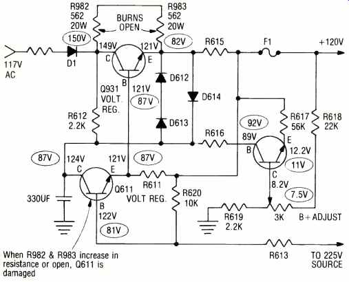
Fig. 10--Insufficient width was noted in this Channel Master model 6125.
The voltage adjustment would not pull the raster out to fill the screen.
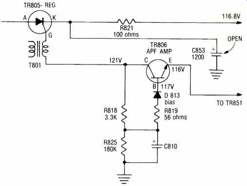
Fig. 11 --Good sound, and a narrow picture were the symptoms of a J. C. Penney ETA -3 chassis. Only 98 volts was present at the low voltage
supply output
Intermittent width
Intermittents in the power supply may take a little longer to find than no or low voltage. Monitor the output voltage at all times. When the supply acts up, you can see the variation of the output voltage.
The voltage may go to zero for no raster or as low as 80 volts for a narrow picture.
Between the two, the intermittent raster is easiest to locate.
Most intermittents are caused by transistors and resistors. You may also encounter a defective electrolytic capacitor. Try not to disturb any component until you have located the defective one. First suspect open transistors. Check for zero voltage at the emitter (Fig. 6), especially if the power active filter transistor is the flat type.
These transistors are noted for internal opens. Wiggle the transistor terminals and see if the transistor "pops" on.
Suspect coupling capacitors in thyristor type circuitry. A pulsating raster may be caused by a large electrolytic filter capacitor (800 mfd or larger). The B+ voltage may go below 80 volts in an intermittent width situation. In simple voltage regulator circ. ,its, suspect a power transistor. A power filter transistor may open causing the narrow raster.
Check for overheated resistors and poor pc board connections. The wiper contact of the voltage adjustment controls have been known to be intermittent.
Keeps blowing fuses
If the main fuse blows each time a new one is inserted, suspect an overload caused by outside circuits or within the power regulator circuit. Sometimes a fuse is found in the output voltage load circuit. If this fuse is not blown, suspect the power supply. Generally, the load fuse will blow first, if an overload occurs in the horizontal output circuits.
A constant blowing of the main fuse may be caused by low voltage rectifiers.
In bridge rectifier circuits, unsolder one lead of each diode for leakage tests.
Suspect a shorted thyristor or SCR when one is used in the voltage regulator circuit. A direct short between terminals A and K will automatically blow the line fuse (Fig. 8). Also, check for a leaky active power filter transistor.
Leaky filter capacitors may cause the line fuse to open. These capacitors can either dry up or short internally. Check for low resistance reading across the suspected capacitor terminals. Remove the positive lead to determine if the capacitor is leaky. Always choose equal or higher capacitance when shunting another electrolytic capacitor across the suspected one.
Weak FM, choppy AM
A Monteverdi model CG001-0014 radio came in with weak FM and choppy AM.
Sometimes the local AM stations would not tune in at all. We noticed the RF transistor (Q1) and FM -AM IF IC (AN277) had both been replaced.
All voltages on the AM and FM RF transistor and the IC were from 1 to 3 volts lower than indicated on the schematic. Checking back into the supply, we found only +7.7V where we should have found around 11 volts (Fig. 9). Here we suspected a defective voltage regulator transistor Q8 (2SC1383). Voltage measurement found the collector voltage normal (20V) but the cathode and base terminal voltages were about 3 volts too low.
The voltage regulator transistor was removed and found leaky. But, replacement of Q8 did not solve the whole problem. The 12 volt zener diode was found leaky. When it was replaced, the voltage source measures 11.5 volts.
Replacing the voltage regulator and zener diode restored the FM reception.
Readjustment cured the choppy AM reception.
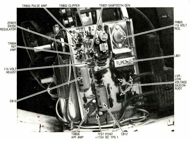
Fig. 12--Here is a photo layout of a Panasonic ETA-1 chassis which is
found under J.C. Penney and other labels.
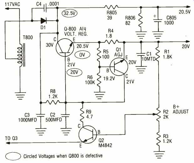
Fig. 13--A dead Motorola 18TS-929 hybrid chassis came in with the main
relay not energizing because of an open pass transistor in the low voltage regulator.
Insufficient width
The right side of the raster was pulled in about 1/4 of an inch in a Channel Master 6125 TV model. The voltage adjustment in the low voltage power supply had no effect upon the narrow raster (Fig. 10).
HV measured normal. The low voltage source, however, was only 89 volts, while it should have been about 120 volts.
First, all transistor voltages were recorded on the schematic. They were all low except the voltage (150V) on the collector of Q931. Since the voltages were all low and quite close, Q611 was suspected of being defective. It was removed from the circuit and found to be leaky, and replaced with an RCA SK3124.
The output voltage came back up to 120 volts but after two minutes the narrow raster was back again. We found Q611 too hot to touch. A closer examination of the pc board turned up R982 and R983 (20W) resistors as possible suspects. These resistors run quite warm and sometimes melt the solder upon the pc board. If either one opens, Q611 will be destroyed. Both resistors were removed, checked and replaced with re-tinned leads.
Replacement of both resistors and Q611 solved the narrow raster problem.
When large wattage resistors are found across the voltage regulator transistor, remove them and check for correct tolerance. Also, reset the voltage control to the correct voltage.
Good sound--narrow raster
Besides funny lines in the picture, this J.C. Penney 2877 model had a narrow raster (Fig. 11). The sound was normal.
Only 98 volts was found at the supply output. The 115 volt adjustment (R816) would vary the voltage source about 5 volts. The horizontal output transistor (TR551) was removed to eliminate the possibility of an overload caused by the horizontal section.
In this particular chassis R819 (560) was burned beyond recognition. After R819 was replaced, it ran too hot to touch. The active power filter (APF) amp (TR806) was removed and tested good.
While it was out of the circuit, diode D813 checked normal. The APF output transistor (TR851) was removed and tested okay.
(1200 uF) was shunted, the raster returned to normal. It solved the overheating of R819.
There have been many other problems occurring in this same Panasonic power supply. When the circuit breaker keeps kicking out, suspect a shorted or leaky thyristor TR805 (2SF248) in a Panasonic ETA -1 chassis. Check for a high leakage or a short between terminals A and K with it out of the circuit. A good thyristor will measure above 50 megohms between A and K. You may find 50 ohms between K and C terminals; this is normal.
When no output voltage is found at S4 (+115V) suspect problems in the regulator system (Fig. 12). Measure the voltage at the anode terminal of TR805 which should be around 107.5 volts. If no voltage is found at the cathode (K) terminal, go directly to the sawtooth oscillator (TR801) with the scope.
Check for a sawtooth waveform at the collector terminal of TR801. Take voltage measurements when an improper waveform is found. You may notice the voltage at all terminals of TR801 are the same. A leaky TR801 will not oscillate and will apply incorrect voltage to TR802. When TR801 is leaky, the base and emitter voltage will increase to the 38.5 volts of TR802 and there will be zero voltage on the collector terminal. Use the scope to locate the defective stage and back it up with voltage measurements in this type of voltage regulator.
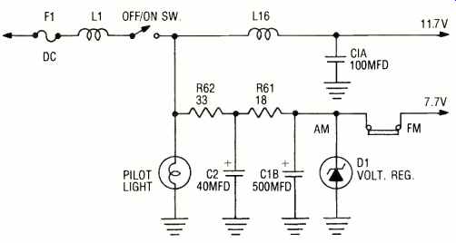
Fig. 14 --Here is a simple voltage regulator circuit found in a car radio.
A dead Motorola
There was no life in this Motorola hybrid chassis, 18TS0929. In this model a dc relay must close to apply operating voltage to the circuits. Since the relay did not energize, the dc voltage source (20V) was traced back to the low voltage regulator circuits (Fig. 13). Adjustment of the B+ control R2 would not help the situation.
Voltage measurements were taken upon the voltage regulator transistor (Q800). The collector voltage was normal, but 20 volts on the base and zero volts on the emitter were noted.
Q800 was removed since it was suspected of being open. It tested good.
Since these flat type transistors have a tendency to open up internally, a SK3054 transistor was installed and solved the problem.
Comments
Today, in line -operated ac chassis you may find service problems in the low voltage power supply. A quick voltage check may indicate that the trouble lies in the regulator circuits. Always try to adjust the low voltage adjustment control and set it to the required operating voltage. You may find leaky or open regulator transistors cause most of the problems. Suspect out of tolerance large wattage voltage dropping resistors in the power supply circuits. Isolate the horizontal output section to determine if the trouble lies in the low voltage regulator system.