Here is a continuation of last month's review of ac theory and an examination of series and parallel ac circuits.
by Stan Prentiss … from an unpublished book "Today's Electronics--Electronics for Troubleshooting" .
Pretty soon we'll be dealing with impedances as complex quantities since they have both resistive and reactive components as well as phase angles. Therefore, we'll have to know not only the magnitude of the resistive and reactive impedances but their phase angles as well. A graphic approach is very convenient.
Vectors
Equations will do the same thing as pure vector diagrams, but with fundamental series and parallel circuits, the vector graphic approach is much simpler and quicker. Actually, it would probably be easier to introduce polar and rectangular coordinates and their conversions immediately with vectors, but it may be just a little too much to grasp all at once, so we'll save this for ac circuit analysis which is coming shortly.
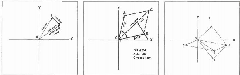
Fig. 1. An elementary diagram illustrating the addition of two vectors by
simple addition.
Fig. 2. A second method--by parallelogram--to find the phase angle and magnitude of simple vectors.
Fig. 3. Three forces acting on 0, the origin simultaneously. Use the same method twice. Double line 0 to 5 is resultant.
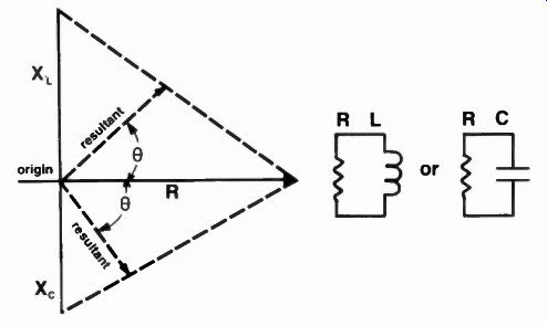
Fig. 4. A vector of the same resistance in parallel with one inductor or one
capacitor.
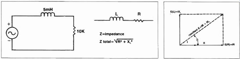
Fig. 5. A series LR circuit with ac generator.
Fig. 6. Vector sum of current/voltage IR drops in the RL circuit of Fig. 5. Measured phase angle θ is 36° between current and final voltage.
Vectors are useful in finding what is known as a resultant, and this means the complex sum of two or more magnitudes or forces going in different directions. For instance, take a line segment. The length of the line is the magnitude and angular position, while an arrowhead at its tip will tell direction. Let's set up a pair of lines and join them with another line. In Fig. 1, 0 to 1 could be one line segment, and 1 to 2 could be another. Then the line 0 to 2 is the resultant direction and magnitude of the initial two lines and represents the vector sum of both. Of course, both forces must be applied to the same objective and neither the 1st nor 2nd lines may have either their magnitude nor directions changed. Should such occur, then the resultant would be untrue. You may also start both forces at the origin 0 and form a parallelogram to produce the same result-and usually this is how basic vector addition is done (Fig. 2). If you're dealing with more than two forces, then two or more parallelograms must be drawn. The illustration in Fig. 3 shows this. The forces are designated as 1, 2, 3. The resultant of forces 1 and 2 is 4. Then the parallelogram 0, 3 and 4 is formed by the dotted lines and the overall resultant of the three forces is the line 0 to 5.
This looks relatively easy--and it is--but with one considerable exception-your measuring instruments probably aren't accurate enough to provide precise results. However, vector diagrams can quickly show worthwhile approximations and are certainly useful in estimating directions forces will take as well as ultimate phase angles.
A means of determining a single resistance and reactance in parallel should also be illustrated (Fig. 4) if for nothing more than a reference and another way of finding a needed solution. This, by the way, may prove a little more accurate than the previous series methods, but is limited by a single R and XL or Xc For your information, let's do both the XL and the Xc on a single diagram. Two resultants are the magnitudes of the vector parallel addition, and are at right angles to a line drawn between the 90-degree positive phase shift of the inductor and the 90-degree negative phase shift of the capacitor.
Through a resistance, of course, current and voltage remain in phase.
Any reactance and resistance can be done this way by simply plotting their magnitudes horizontally: draw a line between the magnitudes of each, then draw a final connection from the origin, perpendicular to the joining line. You now have the scalar resultant and its direction from the angle (theta). Now, we're ready to begin approaching the meat of the entire article, and that is reactive networks. For the novice, some of this will be relatively heavy reading, but you will now see how we can put everything together.
Reactive networks
Such networks include resistance, capacitive and inductive reactance, impedance, current, voltage, series and parallel resonance, power factor, vectors, polar and rectangular coordinates, and even phase angles.
If there's anything left out, we'll discover it before we finish. The subject of transformers, by the way, may be undertaken later in a discussion of coupling and bypass circuits and transmission lines.
Now, recall Ohm's Law, where E=IR; then substitute the Z expression for complex impedance and make the equation read E=1Z. Then, when E=IZ, I=E/Z = E/Xc = E/XL
So Xc or XL alone can also equal Z and with this in mind, we'll begin with a basic LR circuit and discover some things about it.
A Series LR Circuit
In an inductor, recall that voltage leads current by 90 degrees, because inductors always oppose changes in current with a counter emf. So, if we were to draw a vector diagram of this condition, voltage would be at right angles to current, and current would be in phase with the series resistor.
The voltage, then would be the drop across the inductance (and resistance), and the resultant and its phase angle between current and voltage in the AL circuit would look like it does in Fig. 6. The XL reactance is perpendicular and its voltage is the IXL drop across its impedance Z. The horizontal projection shows current in phase with resistance and, again, the current times the resistance (IR) amounts to the voltage along this portion. The total voltage in the circuit, then, is the vector addition of the IR and IXL drops, and is the resultant, with phase angle between current and voltage represented by theta, 0. So even though XL is a 90-degree phase shift in itself, a Z + R circuit can have an entirely different resultant and finish with a phase angle that isn't even half of what a pure inductance by itself would produce.
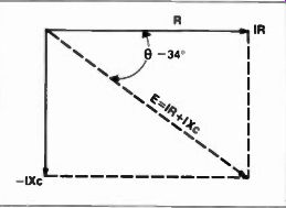
Fig. 7. A capacitive reactance and series resistance produce another rectangular
solution, but the phase direction is now negative.
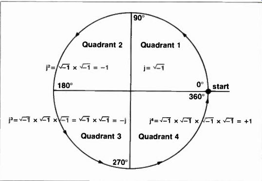
Fig. 8. The j-operator rides again. Each value of/is -1 and amounts to a 90°
counterclockwise rotation.
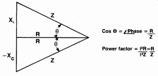
Fig. 9. Positive (X_L) and negative (-X_c) reactance on same diagram. Cos 0
equals RIZ, the phase z between voltage and current. In units between 0 and
1, R/Z is the power factor.
A Series RC Circuit
You can do the same thing with a capacitor-resistor circuit as with an inductor-resistor circuit . . . the chief difference is that the current here is not in phase with the resistance, and even though you can pick out some obvious physical features of both capacitive and inductive circuits such as the value of these components and probably the frequency that's applied, there is yet another element that must be accounted for. This is operator j, the 90-degree phase shift sign that has numerical characteristics in the four quadrants, depending on the number of times it rotates, so evident in Fig. 8.
Initially, of course, j = -1, j 2 =i- lx'11- 1 until, in the 4th quadrant, j4 amounts to +1 ... then the entire procedure begins again if we're speaking of a continuous cyclic wave.
Unfortunately, the square roots of negative numbers have been called imaginary and they really aren't at all.
A farad capacitor, for instance, charged to several hundred "negative" volts could do a great deal of damage if it makes the right contact. So to handle a number such as' J" , we could simply write it a 9 -'11, with the positive root outside; although you won't be doing this normally in electronics -at least not in this discussion. Ordinarily, j will just denote the phase shift component which is recognized as R/Z and expressed as Cosine 0. In a circuit containing both resistance and capacitance, as an example, the voltage E =`1E2R + E2C, and the impedance Z =IR2 x2c. Therefore, E zhe = Er - jEc and Z/-0 = R - jXc Also, at this point, we can find the power factor (power dissipated) in a circuit by dividing the true power by the apparent power- pf = true power P/apparent power El or pf = 1 2R/I2Z = R/Z or, using the phase angle between voltage and current: pf = Elcose which amounts to the apparent power multiplied by the fraction (up to 1) that delves from R/Z and becomes the cosine 0 angle. The minus sign, as you saw in Fig. 7, denotes symbolic negative deflection of the Xc reactance. In the vectoral addition that follows, squaring the -Xc quantity simply adds to the squared resistive or other reactive quantities under the square root sign. Then, to remove these positive or negative quantities from under the symbol, simply take the square root of their sum and you're dealing with a real, non imaginary number. For instance: Z = R - jXc _1R2 - jXc2 and, with numbers:
Z =\1102 + 8 2 4 : 16T4 = 12.81 (slide rule accuracy).
Then, to find the cos 0 phase angle of R/Z 10/12.81 = .78, and cos .78 =/-38.7° Had the Z been R + jXL, the phase angle would have been 1+38.7° and the impedance would be just the same.
Now, if you also wanted to know the voltages, then the IR, IXc drops across the resistor and capacitor would be quite easy, with the current phase angle always remaining the same in each calculation. Since Z = 12.81, and we can assign a voltage of 30V: 1 = E/Z = 2.34 units, depending on whether Z is in ohms, K ohms, or whatever. But Z = 12.81/-38.7 and the angle divided into E becomes +38.7 for current.
So, IR = 2.34 x 10 = 23.4 units ... and IXc = 2.34 x 8 = 18.7 units .. depending on whether 1 is in amps or milliamperes.
However, across a capacitor, voltage and current are 90 degrees out-of phase. So the voltage phase angle across Xc equals: IXc 0 = -90° = = 18.7/-51.3°
Rectangular & Polar Coordinates
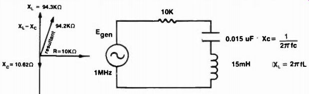
Fig. 10. Schematic and vector diagram of a series RLC circuit pumped at 1MHz.
Note "large" capacitor.
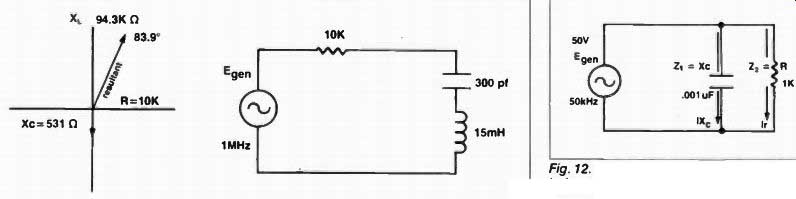
Fig. 11. Same circuit as in Fig. 10 except value of capacitor has changed.
Phase angle has modified somewhat but high frequency keeps X L reactance large.
Fig. 12. An RC parallel circuit where voltage is the constant and current is variable.
In the X, and Xc examples of the previous paragraph (Fig. 3-2B) we have actually been dealing with polar coordinates-in math the X abscissa, vertical points of any line, and the Y, ordinate, of the same line. It is at this point in algebra you begin to solve simultaneous linear equations in more than one unknown. Such solutions may be attained by addition, subtraction, multiplication, and division to eliminate all but a single unknown and then solve by substitution or otherwise for the rest. Unfortunately, since the polar coordinate contains only the sum total of the resistance impedance term, it cannot be used for addition and subtraction; only the rectangular coordinate can. However, the rectangular coordinate forever has the R + jX term that is very unwieldy and its long string of figures, powers, decimals, and j terms contribute to endless arithmetic errors. So what we'll do is to use the rectangular form when (and if) there are instances of addition and subtraction, but the polar form everywhere else. But we will also offer means of mathematically converting between polar and rectangular coordinates when needed, that should simplify most, if not all, problems: Of course 10 + j ( XL) 20 in rectangular would become 4102 + 202 = RFC = 22.35 in polar and the phase angle R/Z or 10/22.5 amounts to cos 0.445 = 63.6° or 22.35/63.6°. But if you wanted to add or subtract the polar 20/35° and 62 /43° it would be necessary first to put them into rectangular form such as this: 20/35° = 20 cos 35° + j20 sin 35° = 20 x .82 + j20 X .574 = 16.4 + j11.42 62/43° = 62 cos 43° + j62 sin 43° = 62 X .732 + j62 X .682 = 45.4 + j42.3
Then the smaller may be either subtracted from the larger or added together, just like in arithmetic:
45.4 + j42.3 (-) 16.4 + j11.42 29.0 + j30.88 or 45.4 + j42.3 (+) 16.4 + j11.42 61.8 + j53.72
In another method, conversion of either of these rectangular forms can be slightly more direct, if you wish to use it. Here, 29 - j30.88 (the negative sign is deliberate for this example) would become:
Tan 8 = -j30.88/29 = arc tan -1.065 = -46.6°
while Z = 29/cos (-)46.6 = 29/.727 = 40.5 so 29 - j30.88 in a rectangular coordinate becomes 40.5/-46.6° in a polar coordinate. Note that the negative sign between the R and j terms carried over into the phase angle. If there had been a positive sign between the R and j terms, the cosine of the angle would have also been positive.
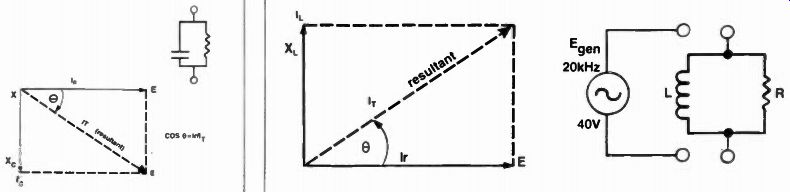
Fig. 13. Vector diagram for the parallel RC circuit
The gross resultant does not indicate a true phase angle. Xc is always shown as the -jXc position of any complex impedance.
Fig. 14. Although the current lags the voltage by 90° through a pure inductor (the opposite of a capacitor), the vector is drawn "upside down" to keep the usual upward X L perspective.
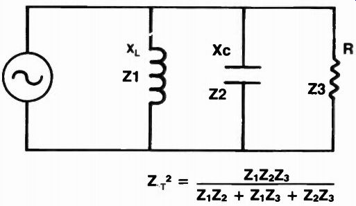
Fig. 15. Total impedance in these parallel circuit is given by Z t , while
current is the vector sum of R, X, c, X L, individual currents.
With division and multiplication, polar coordinates are used exclusively because it is only necessary to multiply or divide the magnitudes and add or subtract the phase angles.
To multiply: 75/12° X 20/30° = 75 x 20/12° + 30° = 1500/42
To divide: 75/20/12° - 30° = 3.75/-18°
Note once more, the negative sign remains when the second angle is larger than the first in division, just as it did in the arc tan 0 above. Naturally, 30° - 12° would become a +18° because the smaller was subtracted from the larger.
RLC Series AC Circuits
We're now ready for somewhat more complex networks in addition to the introduction of frequency, in which actual inductive and capacitive reactances must be calculated.
Selecting a frequency of 1MHz, for instance (Fig. 10), let's calculate the reactance of the three components in series, collect terms, and come up with a working resultant and phase angle:
Xc = ½ pi fC = 1/6.28 x 10^6 x 0.015 x 10^-6
= 1/6.28 x 0.015 = 1/.0942 = 10.62 ohms (almost a short circuit)
XL = 2 pi fL = 6.28 x 10^6 x 15 x 10^-3
= 94.3 x 10^3 or 94.3K ohms
So the circuit's total impedance amounts to:
Z = 10K + j94.3K - j10.62
Now, although the small capacitive term is actually subtracted from the inductive term 94.3K - 10.62, the difference is negligible, so we'll make the reactive portion of the network j94.2K, just to show a small shrinkage.
Consequently, the overall impedance now amounts to:
Z = -0 x 10^3 + j94.2 x 10^3 = (10 + j94.2) x 10^3
And you can now square both terms or take the arc tan 0, whichever suits you test. For exercise, we'll do the arc tan (at slide rule accuracies, of course): First Z = j94.2/10 = arc tan 9.42 = 83.95°
Z = R/X = R/cos 83.95° = 10K/.10^6 = 94.5K/83.95°
So there wasn't much phase shift to that circuit at all because the capacitance was too large. Had the capacitance been 300pF, the phase angle might have altered somewhat and the circuit would not have been quite so predominantly inductive. Let's investigate: Xc = ½ pi fC = 1/6.28 x 300 x 10^-12 x 10^6 = 1/.1884 x 10^2 = 5.31 x 10², or 531 ohms
Now, Z = 10K + j94.3K - j531
Z = 10K + j93.7K j93.7/10 = arc tan 9.37 = 83.9° so really, this value change for the capacitor doesn't help much at all.
Any real change in circuit reactance will have to come from the inductor's XL value or a reduction in frequency.
The heavy reactance of XL will continue to nullify the effects of both resistive and capacitive reactance unless its value is changed--a good point to remember when looking at strange and/or unwieldy circuits. If you wanted a series trap circuit, for instance, where at resonance the series impedance was lowest-really a resistance, you'd follow this equation:
Fr = 1/2 pi __/LC and the same equation also stands for parallel resonant circuits. In the circuit of Fig. 10, L and C would become series resonant at:
Fr = 10.6kHz
... a far cry from the 1MHz we started out with, but which was not intended to be resonant because, if you remember, when L and C become resonant, current and voltage are in phase-and we can't demonstrate cos 6 phase angles under these circumstances.
An RC Parallel Circuit
In parallel circuits, of course, voltages across components in parallel are equal, while currents are unequal, and the total current is distributed among the branch currents. To find each branch current, use Ohm's I = E/Z law, with E being the constant voltage.
Since reactance varies, the currents cannot be the same, and the sum of the currents will then amount to the total circuit current.
I = E/Z = E/R = E/Xc = E/XL (Individual components)
Then, I_T = I1 + 12 + 13 ... etc.
Finally, the overall circuit impedance may then be derived from: Z + E/I,
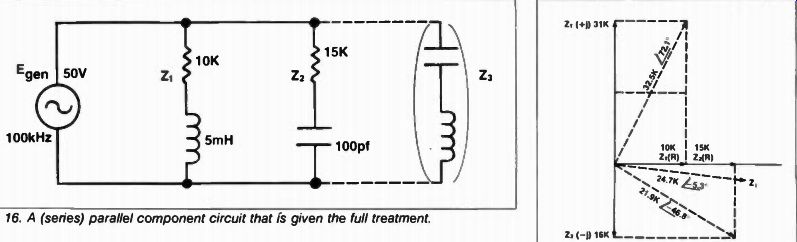
Fig. 16. A (series) parallel component circuit that is given the full treatment.
Fig. 17. The two series impedances in Fig. 16 become one. (The figure is not drawn to scale). F
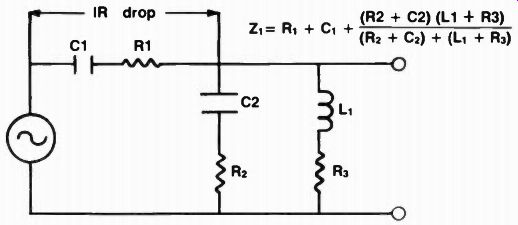
Fig. 18. How to go about calculating a true series parallel circuit. The C's,
and L's, of course, must first be reduced to impedances before their vector
addition or multiplication occurs.
Naturally, you could also add the various impedances in parallel Z, = 1/Z1 + 1/Z2 + 1/Z3 etc., using either/or resistors or reactances and find the total impedance. And remember, too, that in a purely capacitive circuit current leads voltage by 90 degrees. So with the voltage as a constant in parallel circuits, the variable operations are done with currents, and all vectors are illustrated with reference to the voltage vector since all voltages are equal and in phase and also in phase with voltage across whatever resistors are in the circuit. Now, the total current becomes the vector sum of the branch currents, while the current vector is drawn perpendicularly.
If the frequency is 50kHz and the capacitance 0.001 uF, the reactance (Fig. 12) amounts to:
Xc = ½ pi fC = 1/6.28 x 0.001 x 10^-6 x 50 x 10^3 = 1/6.28 x 10^-6 x 50 x 10^3 = 1/6.28 x• .5 x 10^4
Xc = 1/3.14 x 10^4 = .318 x 10^4 or 3.18K so; I I = E/Z1 = 50V/3.18K = 15.72 mA
12 = E/Z2 = 50V/1K = 50 mA
Now since this is NOT a simple dc circuit, these currents add as vectors, and so we proceed directly to the old square root equation:
I t = Ilir2 Ic2 '45 02 + 15.722 x 10^-3 =f2500 + 247 =IY7,- x 10^-3 I, = 52.4 x 10^-3
Securing the total current, the resultant can be drawn as in Fig. 13, but the phase angle should be calculated and, as usual, the cosine is used. Instead, however, of using Z, which is not now the resultant, it becomes the quantity below the line.
Therefore: Cos 0 = 1,./1, =12/IT = 50 x 10^-3/ 52.4 x 10^-3 = 0.105 Cos 8 = 83.97°
... and this is the phase angle between voltage E and current I. If you wish, you may use the sine of 6 and 1,/1, and derive the same result.
To find the impedance, simply use Ohm's law: Z = E/I, = 50V/52.4 x 10-3 = .962 x 10^3 = 962 ohms
Rectangular solutions for this same impedance are not only possible but also useful in situations where conditions are not as straightforward as in the above example. And just as current cannot add arithmetically in parallel circuits, impedances cannot either; so the Zs are calculated in parallel just the same-and we need rectangular coordinates (polar can neither add not subtract) to do the job.
Here, our individual impedances can be written:
Z1 = 3.18K or Z1 = 0 - j3.18K Z2 = 1K orZ2 = 1K + j0 and Z, = Z1Z2/Z1 + Z2
Consequently, = (1K + j0) (0 - j3.18K /(1K + j0) + (0 - j3.18K) Zt = -j3.18K2/ 1K - j3.18K then you must take the conjugate the means of matching one reactive circuit with another by multiplying by its opposite complex reactance-and rationalize the denominator.
Zt = -j3.18K2 (1K + j3.18K) (1K - j3.18K) (1K + j3.18K) Z
= -j3.18K3 - j 210.1K3 / K2 - j 210.1K2
= 10.1K - j3.18K/1 - (-) 10.1 or 10.1K - j3.181Q11.1 Z t = .91K - j.3K
Or, in polar coordinates1.912 - j.32 (K) =t8281 + .09 (K) = .952K or 952 ohms For slide rule accuracy, that comes pretty close to the 962 ohms originally calculated by the simple method-only 10 ohms difference.
The phase angle, using the rectangular coordinates now becomes:
Tan 0 = .3/.91 = .33, or 18.5°
If you need a moral to rationalize these two ways of calculating the impedance totals, with their slight differences; it is always desirable, if possible, to use the simpler approach.
Slide rule errors and arithmetic mistakes can and do make a difference. Obviously in almost 1,000 ohms, 10 ohms is not catastrophic. But if the impedance had been 100 ohms, then the 10 ohms miscalculated could have meant a 10 percent difference in the response of the circuit, perhaps much more. Calculators, of course, will help equalize the probability of human error when complex methods have to be used.
Power factor, as usual, is the cosine theta: R/Z, = .91/.952 (K)
pf = cos theta = .957 or 95.7%
An RL Parallel Circuit
An inductive-resistive circuit similar to the RC parallel combination described in the last paragraph is illustrated in Fig. 14, along with its vector waveform. The purist would describe both Figs. 13 and 14 as "upside down," but convention always shows Xc drawn downward and XL upward, and a change here, even for the sake of current leads and lags, might be confusing ... so it shan't be done.
Apply clockwise operator j if logic must be overwhelming, or you could transpose the E, Xc, and XL axes and do the same thing using courter-clockwise j. At any rate, we'll stand with what's laid out.
Of course, voltage is again the same value across both impedances and remains the constant or reference vector, and Ir has the same phase as voltage E (40V). So if, at a 20kHz frequency, the reactances assumed amounted to: R = 1.5K and XL = 7.5K, which becomes Z1 and Z2, respectively.
Then Ir = 40/1.5K = 25.7 ma and I L = 40/7.5K = 5.34 ma
Now Z, = Z1Z2/Z, + 22 and can be done by the simple method or by rectangular coordinates.
To aid the reader, we'll again do the calculations by rectangular coordinates.
Z, = (1.5 + j0) (0 + 7.5 k/ (1.5 + j0) K + (0 + j7.5) K
= j10.25/1.5 + j7.5 K (multiply by conjugate)
= j10.25 (1.5 - j7.5)/(1.5 + j7.5) (1.5
- j7.5) K
= j15.4 -j277/2.25 - j 256.2 = 77 + j15.4/58.45 Z, = 1.32 + j.264 K
Then for phase angle,
Tan θ = .264/1.32 = .2 = 12.3° or Cos θ = 101, and I =4Ir2 + IXL = 25.72 + 5.342 (mA) =4. 6T3 0 = 26.2 mA
Then I, = 25.7 mA/26.2 mA = .982 and cos .980 = 11° + about 1
Not quite an exact check, but within about 1 degree nonetheless, all slide rule accuracies.
RLC Parallel Circuits
In complex parallel circuits, just as in simple parallel circuits, the total current is always the vector sum of the individual branch currents, regardless of how many parallel elements are in series in each branch.
The impedance of each, then, must be round, followed by its total impedance, then the rectangular or polar coordinates calculated to solve for phase angles and the remaining information. It's only necessary to remember that you're thinking in terms of currents and impedances rather than, in series circuits, voltages and impedances. As an example, if there are three or four single parallel impedances, the I subtotal current though each is the simple Ohm's law of each Z subtotal impedance divided into the constant (source) voltage. The total current is then the parallel sum of these impedances, as shown in Fig. 15, divided into the steady-state voltage. And it is found by the vector addition of the three currents shown:
I_t =__/ Ir^2 + (IXL - IXc)^2
Then the phase angle is simply cos θ= I_r / I_t
Let's carry this idea somewhat further and look at a series parallel circuit with a full compliment of RCL components and an LC pair on the tag end for good measure.
RLC Series-Parallel Circuits
The new circuit is exhibited in Fig. 16 and has inductors and resistors in series as well as the possibility of another parallel LC circuit on the end.
This will not be calculated, however, because Z1 and then Z2 would have to be seriesed and paralleled and then Z, would then become the parallel impedance of Z3 with that derived from manipulations of Z1 and Z2. So we'll just use that of Z1 and Z2 as sufficient illustration. With an R in Z3, however, this would simply become a jXL - jXc, and the R term would amount to 0. So if Z3 became, for instance, j26K, then the entire term would become 0 ± j26K, depending on whether the inductance or capacitance prevailed in overall magnitude. Work it out for yourself, if you'd like to tackle three impedance equations as suggested in Fig. 15. It might not be as difficult as you think, just a little tedious. Here, at 100kHz, the XL and Xc reactances are calculated as:
XL = 2 pi fL = 6.28 x 105 x 5 x 10^-3 31.4 x 10^2 or 34.1K
Xc = 1/2 pi fC = 1/6.28 x 10^5 x 100 x 10^-12 = 1/.628 x 10^4 =16K Xc = 1.59 x 10^4 = 15.9K-ohms rounded off to 16K and 31K,
...respectively for Xc and XL.
Now the series impedances are found by the straightforward polar method:
Z1 = 10K + j31K =4100 + 961 = 32.5K
Z2 = 15K - j16K =4225 + 256 = 21.9K
... and the cos θ phase angles amount to:
R/Z1 = 10K/32.5K = cos θ = .308 = 72.1°
R/Z2=15K/21.9K = cos 8 = .685 = 46.8°
This is a good comparison between resistance and series impedance: the greater the difference, the wider the phase angle; the less difference the smaller phase angle--and, as you see, either R or the final series impedance can be the decisive factor, since either frequency or the magnitude of R or jX can have a determining effect.
The parallel impedances of Z1 and Z2 with their resultant phase angles now need to be calculated so that the various currents through the impedances can be found. Of course, current in any one branch is also the series current and passes through both series resistance and reactance equally. Using the basic parallel equation:
4 = ziz2/zi + z2 Z, = 32.5K/72.1° X 21.9K/-46.8° (10K + 15K + j31K - J16K)
(polar coordinates divided by rectangular coordinates)
712K2/25.3° 25K + j15K 712K2/25.3° 29.151(131° (Tan. j151Q25K = .6 and 31°) Z,=24.7K/-5.3°
In this instance, 31° brought from below the line becomes a negative phase angle, and this must then be subtracted from 25.3° to determine the final direction of Z, whose magnitude has already been calculated as 24.7K. This same mechanical numerator denominator arrangement holds also for currents and voltage drops across the reactances, if you wish phase angles.
The voltage, however, is 0, so any phase angle below the line is just itself with a reverse sign when above the line is zero. For instance: 50V1.0_ 24.7K /5.3° I, = E/Zt = 2.025 mat 5,3f
= E/Z, = 50V/32.5K/72.1° = 1.54ma/-72.1 12 = E/Z2 = 50V/21.9K/-46.8° = 2.28ma/46.8
The IR, IXL, IXc voltage drops can then be found by multiplying the currents through each impedance by the reactance of the impedance, and the phase angles found similarly except to remember that the inductor has a +90° phase angle, and the capacitor a -90° phase angle. So they will add to or subtract from each current accordingly.
As an example: Ec = I2Xc = 2.28 X 10⁻³/ 46.8° x 16K /-90° = 36.5V/-43.2°
Work out the remainder for an exercise, and draw the vector diagrams also, if you wish. You would approach a true series-parallel circuit as shown in Fig. 3-18, adding the resistances and reactances of the series components first, then paralleling the remainder. Remember, however, there would always be a voltage drop across R1 and C1, so the steady voltage for C2, L1, R2, R3 would be somewhat less than the E generator voltage at the origin.
(source: Electronic Technician/Dealer)
Also see: Link |