
Have you ever replaced a transistor with the substitute recommended in one
of the replacement guides? Did it work -sort of-but not quite right? Here are
some of the reasons why substitutes don't always work. The semiconductor guides
are not infallible.
by Bernard B. Daien
For many years technicians have been making vacuum tube substitutions. More recently, semiconductor substitution manuals have become popular, like the older tube "subber" manuals. Unfortunately, semiconductor substitutes, like tube substitutes, don't always work out satisfactorily.
Of course there are reasons why this happens, but most of us don't bother to pursue those reasons ... which results in repeating the same mistake over and over. Once you know the main factors affecting semiconductor substitution, you can avoid most of the problems.
Semiconductor substitution "detective work" is becoming an increasing factor in servicing, with many shops reporting as much time spent that way as in troubleshooting and actual repair! Thus there is a real incentive, in time and money, for learning the basics of substitution.
Many shops are paying needlessly high prices for substitutes, because they have no confidence in their own ability to do the job, and therefore must rely on the recommendations in "subbers." This article explains the basic facts regarding transistor substitutions, and is useful to anyone making such substitutions.
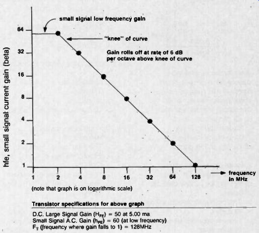
Fig. 1 Transistor gain/frequency characteristics.
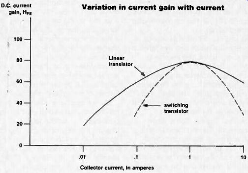
Fig. 2 Transistor current gain variation.
Bipolar Transistors
This first article on semiconductor substitution is devoted to bipolar transistors, since they are the most commonly encountered devices, and also the least complex, and therefore a good starting point. Perhaps their very lack of complexity is what causes most of the problems in substituting, since technicians tend to treat them too lightly ... and in order to deal with them, one must go back to the very basics ... (which most of us have either ignored, or forgotten from lack of use!). Before we go further it should be pointed out that semi-conductors come in two main categories ... registered devices, which have 1N ... , 2N , 3N , or 4N ... numbers.
No matter which manufacturer makes these devices they are the same in the essential characteristics registered. Then there are the non-registered devices, sometimes referred to as "house numbers" because they are made to the specifications of the house which manufactures them. There is no obligation on the part of other manufacturers to duplicate their essential characteristics. Thus when you buy a house number you are relying upon the word of the maker... perhaps the "advertising" of the maker would be more specific and accurate.
Even registered devices vary somewhat from maker to maker... but in general the major characteristics are well defined, while the lesser ones are often permitted to exceed in quality the specified problem, since sometimes "more" is not "better." Thus a transistor which has a better frequency response, may develop parasitic oscillations when used to replace a device with a narrower bandwidth. The narrow bandwidth semiconductor simply did not have enough gain at high frequencies to oscillate. The new device may now require parasitic suppressors of one sort or another to make the circuit stable.
Some Suggestions
This leads to a few, simple rules: It is risky to replace transistors in tuners i FM or TV sets with anything other than the original part, (if it can be obtained). It is better to wait for the original part, than make a quick fix with a substitute. AM broadcast receivers are not too critical and substitutes can usually be used with a high degree of success.
Since TV IFs run at 40MHz, it is advisable to use exact replacements, while FM and broadcast receiver IFs can often be substituted IN THOSE STAGES WHICH DO NOT HAVE AGC APPLIED. Whenever an AGCed stage is replaced it is good practice t use an exact replacement part. There are several reasons for this .. . first, AGC is accomplished in two different ways, "forward AGC" which increases the current through the device, or "starvation" AGC which reduces the current towards cut-off. These different AGC methods result in different effects ... the input impedance is much higher with stravation AGC than with forward AGC. Similarly, the capacitances vary differently depending upon the way the device is made, and upon the AGC employed. This capacitance variation is very important; it is actually part of the set design, since it affects the IF response curve. Generally, TV set makers want the response to "peak-up" (become triangular instead of flat-topped, as the signal gets weaker. This reduces the higher video frequencies (snow) on fringe signals. The loss of color is of no consequence since the color killer cuts off the color on weak signals in order to avoid "colored snow." If the transistor being AGCed has the wrong characteristics, the band width of the IF may actually increase on weak signals, accentuating the snow, and making weak signals worse. Even worse, the IF may oscillate, or refuse to permit a decent alignment after part substitution.
I vividly recall an RCA TV set which blew an AGCed IF transistor. I figured that if I used the RCA SK manual, and the recommended RCA substitution, it would be a safe substitution . . . all RCA. But the set wouldn't align, and oscillated. Upon replacing the device a second time . . . this time with the original part, it lined up and was stable on the first attempt.
Another reason for not using substitutes in the front end (tuner) section of receivers is that there is a little specification called "noise figure," which is the figure of merit of the device in such applications. The lower the noise figure, the better the device is ... i.e., the less noise it contributes.
Since the incoming signal is weakest in the tuner, and since any tuner generated noise is amplified by the rest of the amplifier stages in the set, it is essential that the noise figure of the semiconductors in the front end be as low as possible. Substitutes often do not even have specs on noise figure! Many set manufacturers buy their transistors to their own manufacturing specifications; the front end devices often are specially selected for low noise. Since the set maker buys in large quantities, he is able to get this extra service at little extra cost ... but you can't! Again, use an original part.
Another area where indiscriminate substitutions can lead to odd problems is in high level video amplifiers, which must put out rather large signal swings. These stages have a variety of different frequencies to amplify simultaneously, and at high levels there is a strong tendency towards cross modulation and intermodulation, with the consequent generation of spurious frequencies (mixing action) due to non-linearity. Such stages are usually specified to have low non linearity at high current and large signals. Again, you do not have access to such test results to aid in device selection, so it is better to use an original pan.
The Original Is Not Available
Often, on private label brands, older sets, imported sets, or sets made by companies no longer in business, the original part is not available. In such cases the next best thing is to use a part from another manufacturer, which is used for similar application. Thus the high level video amplifier from an RCA set will probably work well in the high level video stage of another make of set, if the voltages are similar. Tuners are often quite similar ... and in some cases identical, since some tuner manufacturers sell their products to several set makers. Some Japanese set makers provide sets to private label makers. There are often several sources of identical, or similar parts.
Remember, most of the substitutes shown in "subber" manuals have been made on the basis of theoretical "paper" comparisons, not actual operating tests, and therefore do not have a high degree of reliability in practical servicing.
There are some applications where you can make substitutions with a good degree of success however ...
When You Can Substitute...
The audio amplifiers, sync separators, low level video amplifiers, low level chroma stages, voltage regulators, etc., are candidates for successful substitutions. All have certain things in common, .. . they do not deal with very low level signals requiring low noise figures ... they do not deal with very high frequencies, . . . and they do not deal with very large signals. They can be described as "run-of-the-mill" applications, and as such, run-of-the mill transistors will suffice. Since this is where most of your substitutions will be made, you can stock a few types of transistors, in fairly large quantities, taking the advantage of volume buys to keep prices down.
Long ago, most service shops discovered that it did not pay to buy rectifiers in varying voltages and amperages, although a 600 volt 1 amp rectifier is less expensive than a 1000 volt 3 amp rectifier. Practically all the TV shops buy, and stock, the 1000 volt 3 amp rectifier since it covers all TV power supply rectifier needs in tube type sets. (Of course that picture will change as the tube sets vanish and are replaced by the new solid state sets). Similarly, for a few pennies more, you can buy small signal silicon NPN and PNP transistors rated at 60 volts Vceo, and 500 ma Ic, with Fts of 100MHz or higher. .. and that is the equivalent of the 1000V 3 amp rectifier. In power transistors you may find most of your problems are in the different packages used, metal ... a variety of plastic shapes, etc., ... however, it would be safe to stock the metal 103 packages in NPN and PNP silicon types in a 80Vceo, 15 ampere type rated for 4MHz Ft, as a general purpose workhorse.
What's All This Vceo And Ft Stuff ...
Now we must go back, briefly, to some transistor fundamentals.
Transistor maximum voltage ratings are specified in different ways. Vceo is the rating with the base circuit open
... the worst case, and the only one to use for servicing, where we always seem to deal with worse cases. Vcb is the rating using the collector and base junctions only, as a diode, and is the best case, and very optimistic. Vcer uses the transistor with a low value of resistor connected between base and emitter, and is also quite optimistic.
Vces is with a dead short between base and emitter, and is the same as Vcb. Vcex actually puts a reverse bias between the base and emitter, and is useful only in switching applications.
The way a typical transistor's ratings might vary, depending upon which of the above is used, would be: Vcb 100V, Vces 100V, Vcex 100V, Vcer 80V, Vceo 60V. ALWAYS LOOK FOR Vceo RATINGS. You cannot compare different ratings.
As for Ft . . . Ft is the frequency where the transistor beta has fallen to unity (one). It is a high frequency.
Referring to Figure 1, you will notice that two specifications are given for most transistors... a low frequency "small signal gain," hfe (beta), and Ft, the point where the gain has dropped off to one as the frequency is increased. There is also a "large signal" gain, given in capital letters, HFE, and this is the dc gain (beta) which we are not concerned with now.
Figure 1 shows the gain curve, for the transistor described in the specs below the graph. We'll disregard the dc gain, but use the small signal gain spec to establish the low frequency gain. We put Ft at the current gain point of "one" on our graph, and then work backwards, knowing that the current gain will double each time we cut the frequency in half. In this case, with an Ft of 128MHz, the gain (beta) is "one," therefore at 64MHz the gain will be two, at 32MHz 4, at 16MHz 8, at 8MHz 16, 4MHz 32, etc., until we reach the low frequency small signal gain point of 60 which occurs at about 2MHz, and then the gain remains flat as the frequency is lowered. Stated another way, the "knee" of the response curve is 2MHz, and rolls off at the higher frequencies at the rate of 6 decibels per octave.
This educational graph also tells us that Ft is not a very practical figure in our business, since we rarely deal with an amplifier stage with a current gain of unity! As a matter of fact, if you wish to deal with a 40MHz IF stage, you had better use a transistor rated for around 400MHz, since the gain will only be a little over 8 at 40MHz (you figure it out now that you know how!). Likewise a TV tuner running at 200MHz will require transistors with Fts around 1200MHz to have to have useful gain at the frequency of operation! I can almost hear some of you saying, "I don't have any real problems with transistor substitutions, most of tile time they run smoothly" ... but it's one thing to say that it "works" and another thing to be able to state that the set still meets original performance specs. Too many sets that "work" are snowy on weak signals, do not perform right on very strong signals, etc. Do you test your sets on weak and very strong signals after making a substitution? Most shops don't. If the shop is in a fringe area, the work is usually checked for fringe performance, otherwise not. If in a cable TV service area, it may be checked for strong signal performance, otherwise not. It should be considered good practice to give any set which has semiconductors substituted, a performance check, instead of an "eyeball checkout." Many shops have discovered that certain transistors appear to be very good buys... unfortunately the cheaper transistors are often those intended for switching use. Switching transistors are not usually tested for linearity, noise, etc. Figure 2 shows the current gain versus collector current curves, for two power transistors, one a switching transistor, the other a linear amplifier. Note that the gain of the switching device drops off at both low and high currents. This is of no consequence in switching applications where the transistor is used either fully on, or fully off, and the drive is more than adequate to insure the transistor being full on. In linear applications, the variation of betas will certainly result in severe distortion, unless a very large amount of inverse feedback is used around the stage.
The above examples were given to make you aware of the problems inherent in transistor substitution ... but there are more. Problems can arise going in the other direction too, using a linear transistor to replace a switching transistor, as in horizontal deflection circuits, where rapid rise and fall times must be accommodated in order to meet the horizontal sweep requirements. If the device used, switches too slowly, the device dissipation will be very high, and the performance poor. Switching transistors are well characterized in rise and fall times, whereas linear devices are not. Many of the better linear transistors can handle fast switching, but may not be able to handle the high voltages inherent in deflection circuits, so once again you may well be ahead of the game by using an original part, designed and characterized for the specific application.
Figure 2 has a few more implications for you. Supposing you are using a complementary symmetry output stage, so popular these days in high fidelity and deflection circuits.
The biasing is fairly critical in these circuits, and prevents crossover distortion. Now if you look at the way the current gain falls off at low currents, you will quickly realize that the biasing required to produce the same collector current, is quite different for the two typical transistors shown. Using a switching transistor will radically alter the quiescent collector current, defeating the circuit design insofar as biasing is concerned.
Other Devices...
Even considering bipolar devices only, every three terminal device is not a transistor in the ordinary sense of the word. Darlington transistors are coming on strong ... and they have only three terminals. If you have a good Darlington, you can spot it by the fact that there are two diode "voltage drops" in series between the base and emitter. .. but only too often the device being replaced is defective and cannot be measured.
Replacing a Darlington with a conventional power transistor often results in the set working . .. but not properly, due to lack of gain.
Dartingtons have gains running from 750 to several thousand ... significantly higher than a transistor, but other than that, they often appear to be interchangeable in many circuits ... again a case of "working", but not meeting original performance specifications. Be on the lookout for this one, as many set makers use Darlingtons with house numbers on them. One clue is to check the bias voltage with a low current drain voltmeter. Darlingtons use twice the normal bias voltage.
Another indicator is the bias current. Darlingtons have less than a tenth of the bias current you would expect to find. Finally, if you have a schematic diagram (which often merely shows a conventional transistor), the input and output signal amplitudes will indicate a greater signal gain for the stage than you would normally expect to find.
Transistor listings often carry Darlingtons simply as "transistor" . . . which can mislead you completely.
What About Diodes?
Diodes are bipolar devices too, and deserve a word here. With the advent of solid state apparatus came low voltage power supplies, and as a result, the rectifier diode drop is now one of the major sources of power loss. The twelve volt systems used in automobiles have much the same problem, as a result alternator diodes are now of the Schottky type, which have significantly lower forward voltage drop than ordinary silicon diodes. Replacing such diodes with ordinary diodes result in enough heat at full load to destroy the rectifier.
These Schottky diodes are now used in many low voltage supplies in apparatus, and you have to be on the lookout for them. They are not ordinarily used in applications where the reverse voltage approached 100 volts, since they are essentially low voltage devices.
Fast switching diodes are used in horizontal deflection circuits in TV sets, as dampers, and as scan rectified power supply devices. They are also used in high frequency power supplies in the usual range of 20kHz to 40kHz. Although occasionally one hears of a technician successfully using an ordinary silicon rectifier in such circuits, the fact is that most silicon rectifiers cannot work in these circuits due to slow turn on and turn off times. Some manufacturers simply make certain diodes which substantially exceed the specification in speed, and which can be marginally suitable for this service. However the situation can change, and the manufacturer is under no obligation to continue making a product that exceeds his specifications. The same type of rectifier made by another source, or a different lot from the same source, may not work. The only safe route is to use a rectifier characterized for high frequency use, and they usually cost more.
Coming up:
The next article in this series will cover FETs, TV high voltage rectifier assemblies, and, briefly, Silicon Controlled Rectifiers.
(source: Electronic Technician/Dealer)