Here are some more teasers for those of you looking to the CET tests.
Good luck.
By Frank R. Egner, CET
Here's another electronics quiz to challenge your knowledge and recall of electronic fundamentals. For example, to answer questions about figure 3, you'll have to recall the basic Ohm's and Kirchhoff's laws to resolve the circuit. Solving dc power supply voltage dividers is necessary to answer figure 4 questions. Do you remember how to calibrate an oscilloscope to measure other than peak-to-peak voltages? And how is your recall on vector or phasor diagrams to indicate circuit relationships? This quiz, like the others, can be an indicator of how rusty you may have become on some of the fundamentals over a period of time. Give it your best effort without looking at the answers.
If you take a few minutes to look up the questions you miss, it'll serve as an excellent review and fundamentals refresher. To make a passing score of 75%, you should miss no more than six questions.
1. An oscilloscope is to be calibrated to measure RMS voltages directly on the volts/division ranges. A tube tester will provide the reference voltage by using the 6.3v ac filament voltage. The volts/division variable control should be adjusted for:
a. 2 divisions on the 10v/div range.
b. 2 divisions on the 5v/div range.
c. 4.4 divisions on the 1v/div range.
d. 6.3 divisions on the 1v/div range.
2. A 9 volt battery will be used to calibrate an oscilloscope to measure ac RMS voltages directly on the volts/division ranges. The volts/division variable control should be adjusted for:
a. 5 divisions on the 5v/div range.
b. 3.2 divisions on the 1v/div range
c. 6.3 divisions on the 2v/div range
d. 4.5 divisions on the 1v/div range
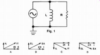
3. The parallel RL circuit in figure 1 is represented by which vector (phasor) diagram below?
4. The conditions in the series RC circuit of figure 2 are represented by which vector (phasor) diagram below?
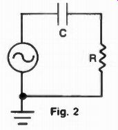
5. In the series RC circuit in figure 2, the phase angle is the angle measured between:
a. ER and EC.
b. EC and Eapp.
c. IC and EC.
d. IT and Eapp.
6. Three capacitors (100pf, 200pf, and 300 pf) are connected in series across a 10MHz, 10v source. The voltage drop across the 200pf capacitor will be:
a. 3.3v
b. 5.7v
c. 2.8v
d. 1.4v
7. Three inductors (2.5mh, 6mh, and 10mh) are connected in series across a 100kHz, 10v source. The voltage drop across the 6mh coil is about:
a. 3.2v
b. 5.4v
c. 1.3v
d. 6.0v
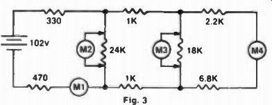
Fig. 3
8. If an ohmmeter replaced the battery in figure 3, the ohmmeter would indicate a circuit resistance of:
a. 6.8K ohms.
b. 9.8K ohms.
c. 11.8K ohms.
d. 24.8K ohms.
9. In figure 3, ammeter M1 will indicate a current flow of:
a. 8.6 ma.
b. 15 ma.
c. 4 ma.
d. 10.4 ma.
10. In figure 3, voltmeter M2 connected across the 24K resistor indicates a voltage drop of:
a. 91.7v.
b. 98.8v.
c. 96.2v.
d. 90.0v.
11. In figure 3, meter M3 indicates the voltage drop across the 18K resistor as:
a. 56v.
b. 83.8v.
c. 67.5v.
d. 60.0v.
12. In figure 3, the current flowing through ammeter M4 will be:
a. 7.5ma.
b. 6 ma.
c. 9.2 ma.
d. 12 ma.
13. A 6 foot length of a certain transmission line has an impedance (Z_0) of 75 ohms. A 30 foot section of this same transmission line will have an impedance of:
a. 375 ohms.
b. 75 ohms.
c. Depends on the load connected.
d. (Z_0) must be re-determined by measurement.
14. An inductor (coil) has identifying dots of brown, black, and orange.
This indicates an inductance of:
a. 1 henry.
b. 0.1 henry.
c. 10 millihenry.
d. 0.1 millihenry.
15. Three inductors (2.5mh, 6mh, and 10mh) are connected in parallel.
The inductance of the combination is:
a. 1.5 mh.
b. 18.5 mh.
c. 6.26 mh.
d. 8.1 mh.
16. A mica capacitor has a six dot color code of black, yellow, violet, black, silver, red. The capacitance is:
a. 470pf, 12%
b. 470pf, 10%
c. 47pf, 12%
d. 47pf, 10%.
17. A high Q series resonant circuit is connected between the load and a 10 volt source. Then:
a. Current through the circuit will be minimum.
b. The voltage dropped across the capacitor will be much larger than 10 volts.
c. An ac voltmeter connected across L and C together indicates 0 volts.
d. More than one but not all of these is true.
18. In figure 4, the resistance of R2 in the voltage divider must be:
a. 1.67K.
b. 1K.
c. 5K.
d. 0.5K.
19. In figure 4, voltage divider resistor R1 should have a resistance of:
a. 833 ohms.
b. 714 ohms.
c. 625 ohms.
d. 1000 ohms.
20. In figure 4, the current flowing through the zener diode ZD is:
a. 20 ma.
b. 5 ma.
c. 10 ma.
d. Cannot be calculated.
21. In figure 4, the ac line voltage increased by 5%. Then:
a. All output voltages increase by 5%.
b. The internal resistance of ZD decreases.
c. All load currents increase by 5%.
d. More than one but not all the above are true.
22. In figure 4, if the load current of the 50v terminal increases by 5 ma:
a. All output voltages will decrease.
b. Only the 100v output will decrease.
c. The 10v output will remain constant.
d. All output voltages, except 150v, will decrease.
23. In figure 4, the power dissipated by R3 under normal operation is:
a. 1.6 watts.
b. 0.4 watts.
c. 2.5 watts.
d. Can't be determined because of ZD. 24. In figure 4, an overload has burned out resistor R2. A 2 watt replacement is installed.
a. This is a proper replacement.
b. This resistor will soon burn out, too.
c. A 1 watt resistor could have been used.
d. A 25 watt resistor should be used to prevent callbacks.
25. In figure 4, zener diode ZD is rated at one watt.
a. If the 20v load opens, ZD will burn out.
b. 1 watt provides insufficient safety margin.
c. The 1 watt rating is more than adequate.
d. More than one but not all the above are true.
ELECTRONICS QUIZ SOLUTION
1.d 2.b
6.c
3.c 8.a
4.b 9.b
11.c 16.d
21.b 7.a 12.a 17.d 22.c 13.b 18.b 23.a 14.c 19.c 24.b 5.d 10.d 15.a 20.a 25.c
(source: Electronic Technician/Dealer)
Also see: CET Quiz VI--Simple Networks