If you read and understood Bernard Daien's article on RC and RL time constants in May ET/D this quiz should be easy.
By Frank R. Egner, CET
RC (Resistance-capacitance) networks are probably the most commonly used component combination in electronics. The simple series RC circuit is used for coupling, differentiating, integrating, waveshaping, and timing to name a few.
RL (Resistance-inductance) networks, although not as common as RC networks, are used for differentiating and waveshaping, plus other applications. How RC and RL networks react depends primarily on their time constants and the frequency and waveshape of the applied signal.
A time constant can be defined as the time required for current or voltage in the circuit to change by 63.2% (usually rounded to 63%) of the maximum possible change. In each subsequent time constant, the current or voltage changes by 63% of the remaining possible change. Therefore, the change follows an exponential curve. After five time constants have elapsed, the change is considered to be completed. The changes in voltage or current in RC and RL circuits always follows the Universal Time Constant Curves (available in most electronic texts). The time constant of an RC network is calculated by the relationship t (in seconds) is equal to the product of R (in ohms) times C (in farads), or t = RC. For example, a one megohm resistor and a one microfarad capacitor have a time constant of one second. In one second 63% of the maximum possible change will occur, and after five seconds the change will be completed.
The time constant of an RL network is calculated by the relationship t (in seconds) is equal to the inductance (in henries) divided by the resistance (in ohms), or t = L/R. Again, 63% of the maximum possible change occurs in one time constant and is completed in five time constants. RL time constants are usually measured in small increments of time when compared to RC time constants, which may range from nanoseconds to many seconds, depending on the application.
To determine how a waveform will be affected by an RC or RL circuit, the shape and period of the waveform must be analyzed with the network time constant. In general, if the time constant is ten or more times the period of the waveform, negligible change in the signal phase, shape, or amplitude will occur. Conversely, if the time constant is one-tenth the waveform period or less, the waveform will undergo a change in phase, shape, and/or amplitude.
The basic operation of both RC and RL time constant effects is best demonstrated by the application of squarewave to the networks. By calculating the signal period (P = 1/F) and the time constant (t = RC or L/R), the output waveform can be predicted.
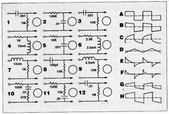
RC and RL network quiz
The following circuits are examples of RC and RL networks. In all cases, the applied waveform is a 10KHz squarewave with 10v p-p amplitude.
By applying your knowledge of time constants, match the output waveforms to the networks that will produce them.
13. In all circuits above, if the input waveform is a sinewave, the output waveform is also a sinewave.
(True) (False)
Answers to quiz
1. b.
2. d.
3. e.
4. f.
5. c.
6. f.
7. c.
8. f.
9. a.
10. h.
11. g.
12. a.
13 True
(source: Electronic Technician/Dealer)
Also see: