The most versatile instrument?
The wideband, dual-trace, triggered oscilloscope is perhaps the most versatile test instrument available for troubleshooting, if you know how to use it, and you must! Here are some principles of its application.
By Robert L. Goodman
If you were just starting in the electronics service profession, what major test instrument would you purchase first? An oscilloscope, most technicians would answer, and you would be quite right. However, in this fast paced electronics age of the 80's you had best make that a dual-trace, wideband width, triggered-sweep oscilloscope.
So, with this in mind, we will now check out various circuits that most electronics technicians encounter every day to illustrate the versatility of this new breed of triggered-sweep scopes that are now available on the today's market.
Refer to the Appendix for examples of the features that are most wanted in oscilloscopes by professional electronics service technicians. This should help you decide which scope is best suited for your particular requirements.
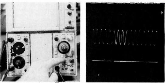
Fig. 1. Tektronix scope with delayed sweep and intensified mode. Fig. 2. An
intensified scope waveform.
Delayed sweep or Delayed Trace
Do I want or need "delayed sweep- or "delayed-trace" on my scope? That is a question many technicians ask.
Thus, there appears to be some confusion about the difference between delayed sweep and delayed trace operation. Many technicians want their scope to have delayed sweep so they can see the leading edge of the pulse that actually "Triggers ON" the scope's sweep or time base generator.
However, to see this leading edge, the scope needs a delayed trace and not a delayed sweep. A delay line in the vertical circuits of the scope compensates for the delays in the triggering and sweep circuits so that the vertical signal reaches the CRT at the exact instant the trace begins its sweep across the scope screen. Thus, most technicians are actually looking for a scope that has a delayed trace function.
In order to have delayed sweep the scope would require two time base generators. These are referred to as time base generators "A" and "B". This feature may be referred to as a delaying time base generator and can become complicated to set-up and operate properly. Delayed sweep lets you expand any portion of the displayed waveform for more detail. Of course, the times 10 expansion (x10) feature in many triggered sweep scopes provides a similar expansion capability with a good bit less complexity. The delayed trace scope allows you to see the details of the triggering pulse's leading edge in digital signal application, with the least operating complexity possible.
Some of the more costly scopes with delayed sweep also have an intensified trace mode. The author's "old faithful" 5403 Tektronix scope is shown in Fig. 1 being switched into the "B" sweep intensified by "A" mode for a detailed look at some complex signals. An intensified waveform is shown in Fig. 2 to illustrate this mode concept. This mode can be used for a better look at a digital pulse train that has been expanded, for example, and in which you may suspect some very faint spikes to be present. The intensified mode will thus make them visible.
Delayed sweep with intensification does have some applications on the service bench, but is more often used by the design engineer in the lab.
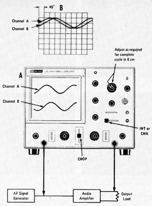
Fig. 3. Set-up for measuring audio amplifier phase shift on an oscilloscope.
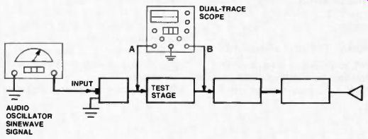
Fig. 4. Test set-up for pin-pointing audio amplifier distortion.
Amplifier phase shift
Phase shifts in audio amplifiers can be measured with a scope. In all amplifiers, a phase shift is associated with a change in amplitude response.
For example, at the 3 dB points, a phase shift of 45 degrees occurs.
Phase measurements can be performed by operating the scope either in the dual-trace or the X-Y mode. The dual-trace mode is used to measure amplifier phase shift directly.
Refer to Fig. 3 for this test set-up. In this set-up the measurements are being made at 500 Hz. The input signal to the audio amplifier is used as a reference and is fed to the A input jack.
The sweep time VARIABLE control is adjusted to provide a complete cycle of the input waveform display on 8 divisions horizontally. A waveform height of 2 divisions is used. The 8 division display represents 360° at the displayed frequency and each division represents 45° of the waveform. The signal developed across the output of the audio amplifier is fed to the CHANNEL B INPUT jack. The vertical attenuator controls of CHANNEL B are adjusted as required to also produce a peak-to-peak waveform of 2 divisions.
The CHANNEL B Position control is then adjusted so that the Channel B waveform is displayed on the same horizontal axis as the Channel A waveform in Fig. 3-B. The distance between corresponding points on the horizontal axis for the two waveforms then represents the phase shift between the two waveforms. In this case, the zero crossover points of the two waveforms are compared and indicates a phase shift of 45°. The second method of phase measurement requires some calculations based on the Lissajous patterns obtained by using an oscilloscope in the X-Y mode.
Distortion due to non-linear amplification can also be displayed by this technique. For these tests a sinewave signal from a function generator is fed into the audio amplifier's input stage.
Isolating Distortion
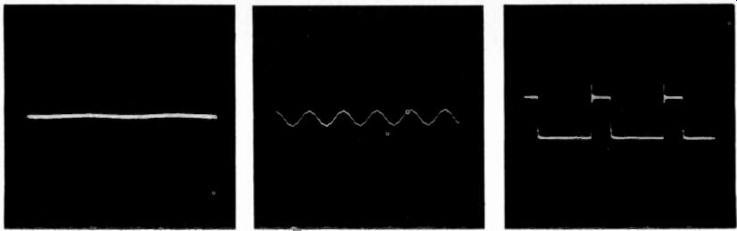
Fig. 5 Smooth trace indicates no distortion.

Fig. 6 This trace indicates some distortion in the amplifier stage being tested.

Fig. 7 Small spike notch (or notch) on leading edge of the pulse is a glitch.
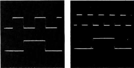
Fig. 8 Proper waveforms for a divide-by-two stage.

Fig. 9 A glitch may cause a divide-by-two stage to divide-by-four.
(Using the scope's "A+B" and "A -B" channel modes)
Let's now see how we can use the oscilloscope to isolate a possibly distorting stage in an audio amplifier.
For these tests we will use the "A +B" and "A-B" display modes. The dual trace scope is connected to the input and output of one suspected stage and then set to cancel the output signal with the input signal. The resulting CRT display will be the distortion introduced by the suspect stage. The audio test signal source used should be a sine-wave, but does not need to have low distortion levels because any distortion in the test signal will also be present at the output of the stage being tested, resulting in cancellation of the test signal source distortion. It is possible to isolate distortion as small as 0.1% using this method because the gain of the scope channels may be increased beyond the level that would cause full-scale deflection, if channel A and B were displayed normally, while the residual distortion signal will remain relatively small on the CRT display.
Pinpointing Distortion
1 - Connect an audio oscillator by feeding its test signal into the amplifier input stage.
2 - Connect the scope's channel A probe to the input of the stage to be tested, and the channel B probe to the stage output. Refer to the set-up block diagram (Fig. 4).
3 - Set the Volts/Division switch for both channels to produce a full-scale signal. Make sure the scope is being triggered properly.
4 - Confirm that the phase of the Channel B signal is OPPOSITE that of the Channel A signal. If they are in the same phase, pull the Channel A vertical position control to invert Channel A.
5 - To obtain an "A +B" display mode, depress both the Channel A and Channel B pushbuttons at the same time.
6 - Adjust the Vernier control of either A or B channel until the trace is as small as possible vertically. This step balances the amplitude of the two traces for full cancellation of the input signal. The resulting signal, that cannot be eliminated with this step, is the distortion, added by the amplifier being tested.
7 - If the result of step 6 is a straight line, as shown in the Fig. 5 scope waveform, there is less than a 2% distortion in the measured signal. The distortion resolution may be increased by ten times (20 dB) by increasing the sensitivity of both channel VOLTS/ DIVISION switches by ten times. If, for example, channel A is set to 1 volt per division, and channel B is set for 2 volts per division, change them to 0.1 and 0.2 volts per division respectively.
To pin-point the trouble in an audio amplifier, check with the scope stage-by-stage, until the stage causing the distortion is located.
The scope trace in (Fig. 6) indicates an audio amplifier stage with some distortion.
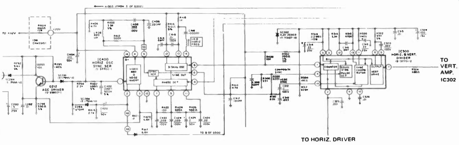
Fig. 10 Circuit for the Sylvania count-down system.
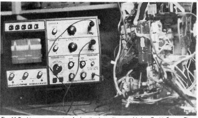
Fig. 11 Dual-trace scope set-up for locating intermittent trouble in a Zenith
System Three receiver.
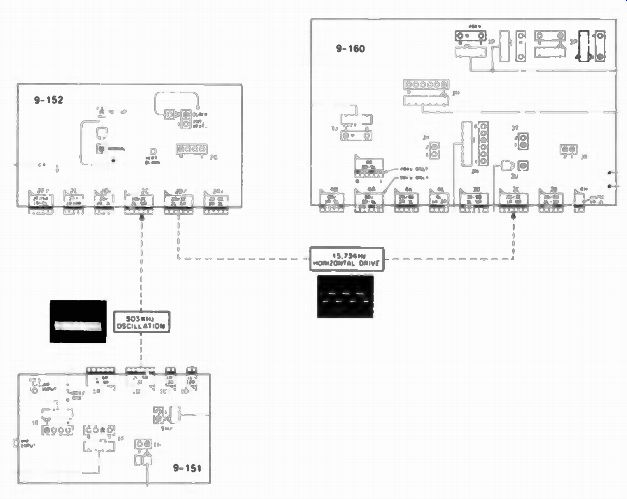
Fig. 12 Diagram of the System Three intermodular signals.
Digital Troubleshooting
A wideband scope is required to effectively troubleshoot digital circuits now found in most modern day electronic devices. Many of these high-frequency digital circuits are used as counting and divider stages in phase-locked-loop systems.
When testing these digital circuits, your scope must show you the true square-wave waveform.
Let's now look at some of the reasons why this is so in checking digital waveforms.
1 - You need to be able to accurately measure the signal pulse amplitude.
2 - You must be able to accurately see the timing relationships of two input signals to make certain the output signal is correct.
3 - You must be able to locate interfering "glitches" that could cause improper circuit operation by adding to the desired input signals.
The "Glitch" Let's now see what a glitch is and how it can affect circuit count-down and divide operation.
Referring to Fig. 7 you will see a scope trace of a signal fed to the input of a digital counting stage. Notice the small spike on the leading edge of the signal. This is a glitch. Glitches are caused by many circuit problems, such as an IC with an intermittent condition, unwanted coupling of signals through the ac power lines, or delays introduced to a signal as it passes through a transistor inside an IC. The glitch does not cause trouble unless its amplitude is high enough to trigger a subsequent digital stage. The scope waveform in Fig. 8 shows the proper operation of the input and output of a divide-by-two stage with out a glitch. The output is a square-wave with a frequency one-half the input.
Now note what occurs when a glitch signal is fed to this divider stage. The digital counter considers the glitch as a separate input signal. The circuit divides the glitch by two, resulting in a narrow spike output instead of the normal square-wave output. At times a glitch may force a divide-by-two stage to become a divide-by-four stage as the digital wave-form in Fig. 9 indicates.
If you were troubleshooting these divider circuits with a 10 or 20 MHz bandwidth scope you could not see these glitches. Thus, this is just one reason you will need a 50 MHz or more, bandwidth triggered sweep scope in order to successfully service logic systems now in use and on into the future.
TV Horizontal/Vertical Count-Down Circuits
The dual-trace triggered sweep scope is a natural for troubleshooting the modern count-down system chips now found in Sylvania, Zenith and other brands of color TV receivers. Let's now check out an actual count-down circuit.
You will find in the Sylvania system, instead of a horizontal oscillator, a 31.5 KHz clock or oscillator signal.
Refer to Fig. 10 for diagram of the Sylvania countdown circuit. The 31.5 KHz clock frequency is twice the normal horizontal frequency of 15,750 Hz. The horizontal sync signal locks the clock to its proper phase. The clock output leaves pin 15 of IC400 and enters pin 1 of the horizontal and vertical divider IC300. The sync signal also leaves IC400 via pin 6 and enters IC300 through pins 4 and 14. If you have picture locking problems, use the scope to check for correct sync signals at these two pins.
In the IC300, the Horizontal and Vertical Driver, the 31.5 KHz signal is divided by 525 (the number of scanning lines) by a flip-flop circuit that produces the 60 Hz vertical drive signal. This signal leaves pin 7 of IC300 and goes to the vertical driver/amplifier IC circuit.
The 31.5 KHz signal is divided by two by another flip flop circuit that produces the 15,750 Hz horizontal drive signal that leaves pin 2 of IC300 and goes to the Horizontal Driver circuit. When troubleshooting this stage use the scope to check the 31.5 KHz input at pin 1 of IC300 and then the vertical and horizontal output signals of this chip after being processed. Thus, should a glitch appear at the input of IC300, the chip may not divide properly and vertical/ horizontal picture lock would be affected. A sufficiently wideband (60 MHz) scope would tell you if there is a glitch or spike present, and pin point the problem area.
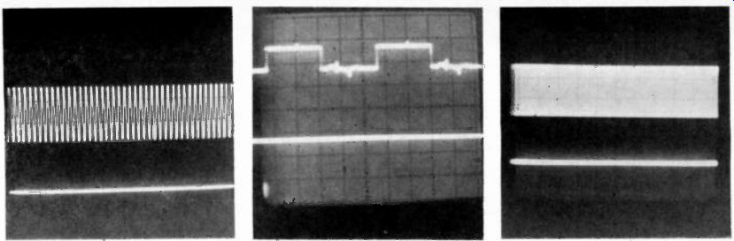
Fig. 14. Correct horizontal drive signal.
Fig. 13. Correct 503kHz master scan oscillator signal.
Fig. 15. The horizontal drive signal is missing on the bottom dual-trace scope
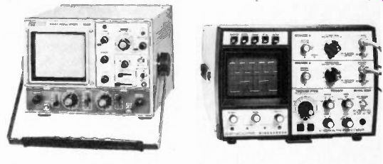
Fig. 16. B&K model 1520 dual-trace scope F photos
Fig. 17. Sencore SC60 WIDEBANDER cope photo.
Fig. 18. Photo of the Telequipment model D83 dual-trace oscilloscope.
Because of the precision count-down circuits used in the above described IC's, the sets using these circuit systems have excellent horizontal and vertical sync that is not disturbed by noise spikes or interference signals. The tip off, to you, for TV receivers that use these count down/divider systems is that there are no customer vertical or horizontal hold controls to be found.
There will be a horizontal or master scan oscillator (clock) adjustment control inside the set, however.
Also note that you will not find a vertical oscillator circuit in these count-down systems. As an example, the vertical signal from IC300 at pin 7 is actually a vertical drive signal and not sync pulses.
Next up, a look at the Zenith System Three count-down system operation and check-out Zenith, System Three, Scope Quick Checks The servicing of the Zenith System Three sets can be a time consuming task if you do not approach the problems systematically. The reason for the systematic service approach becomes more apparent as we look at and then understand the relationships of the various modules in the receiver.
A dual-trace scope will make this faulty module isolation task much easier, especially should you encounter an intermittent problem.
Note the scope bench set-up in Fig. 11 for locating an intermittent problem.
The relationship is such that certain signals from one module to another module must be present for the receiving module to be operative. In fact, a missing or improper master scan or horizontal drive signal waveform can damage components in other receiving modules. As we make these checks refer to the intermodular signals in the Fig. 12 block diagram.
You may find a defective M1 or M2 module could cause a failure of the M10 module. Therefore, before replacing a "defective" M10 module, the M1 and M2 modules should be checked out or substituted. On the M1 (9-151) module, test the 503 KHz oscillation, and for the M2 (9-152) module observe the horizontal drive (15,734 Hz) waveform on the scope.
With a symptom of no raster, no high voltage, with normal hiss in the sound, the following checks should be performed:
1 - Disconnect the yoke plug (3D) on the M10 module.
2 - Turn the receiver on and check with the scope for presence of the 503 KHz oscillation at test point pin 32H or pin 4 of connector 1B on the M1 module. This signal is a 1.5 volt P-P waveform riding on a 2.5 volt dc level, as viewed on a scope. See waveform in fig. 13. This peak-to-peak signal should read approximately 1.2 volts on the ac RMS meter scale.
5 - If the preceding signals are incorrect or missing, replace the M2 module.
6 - If the M1 and M2 modules are providing normal signals to the M10 module, then replace the M10 module, or confine your troubleshooting to the M10 module and yoke circuitry.
Some of these sets may lose the picture and high voltage intermittently.
This may last only a few seconds and occur only every 30 minutes or so. A fault in any of the three modules could cause this intermittent symptom To quickly isolate the problem module, connect one channel of the scope to monitor the 503 KHz signal and the other channel to monitor the 15,734 Hz drive signal. When the trouble occurs see which scope trace is missing. The dual-trace scope photo in Fig. 15 indicates the drive signal is missing and the master scan signal is good. This would point to a faulty 9 152 module. Should both signals he normal then suspect a defect in the 9 160 (M-10) module.
Appendix
Following are some characteristics of typical service scopes of somewhat varying capabilities. Many other manufacturers offer instruments with similar features, among them are in no particular order are: B&K-Precision.
Sencor, and Telequipment and Simpson, Gould, Philips, Hitachi, Hameg, Kikusui, Ballantine. Soltec, Hickok, Leader, Non-Linear, Viz, Vu Data, Hewlett-Packard and Tektronix.
The scopes that follow are typical of those offered to the service industry.
You read the specifications and make your choice.
B&K-Precision 1520
This B&K scope (see photo in Fig. 16) is a high-performance, lab type instrument. It features dual-trace, bandwidth of dc to 20 MHz and vertical amp sensitivity of 5 mv/cm.
The matched, dual vertical inputs let you view, simultaneously, two waveforms. Chopped or alternate sweep operation is manually selected.
Add and subtract capability is also provided so that the sum or difference of two waveforms can be displayed as a single trace.
For video applications such as video tape recorders, CATV and MATV networks, plus TV sets, a built-in sync separator lets you view and lock-in composite video waveforms.
Vector-scope operation is provided for analyzing color circuits.
Features like x10 magnification, electrical trace rotation (adjustable from the front panel), a slotted bezel for mounting a scope camera, and a good looking case will also be found.
Sencore SC60
The SC60 scope's triggering circuits are designed for high stability and ease of operation. (Fig. 17)
There are three reasons for the SC60's stable lock-in features. First, the triggering circuits use differential amplifiers for less noise pick-up.
Second, the triggering circuits themselves are digital, using the fastest available today, Emitter-Coupled-Logic (ECL). And the third reason is that the triggering circuits always operate at a 100 MHz rate, even when you are triggering on an audio signal. This high switching insures such stable triggering that there is virtually no measurable triggering error.
The SC60 will add the two input signals together (A +B) when both the A and B channel display push buttons are depressed at the same time.
Algebraic subtractions (B -A) results if the Channel A signal is inverted by pulling on the VERTICAL POSITION control and both the A and B channel buttons are depressed.
The "A +B" display mode may be used to simplify the comparison of the timing for two signals or phase relationships or making audio amplifier distortion checks.
The SC60 has a TIME-BASE-FREQ switch that is calibrated in both time per division and frequency for 10 full divisions of deflection.
The SC60 scope also has an Vector Analysis Mode for chroma circuit troubleshooting and alignment.
Another time saver is the video preset modes which allows you to select two full fields at the vertical or horizontal rate at the push of a button.
The VITS and VIR signals lock-in very well on this scope due to the special built-in TV sync separator circuits. The checks I have made did not require an external trigger signal to lock-in the VITS signals.
The sync separator has both an amplitude detector and a vertical integrator filter which really locks-in the vertical sync information. The SC60 has a video sync separator for horizontal sync and a second separator for the vertical sync lock-in mode.
Telequipment D83
Shown in Fig. 18 is the model D83 Telequipment scope which can be purchased from Tektronix regional sales offices. This is a dual-trace, triggered sweep scope with a bandwidth of 25 MHz. It has delayed trace and two time base generators with delayed sweep features. This scope has been out several years and is an excellent instrument at a reasonable cost.
These are just some selected features of a few triggered-sweep scopes now on the market, features that are most wanted by professional electronics service technicians. This information may help you decide what kind of scope is best suited for your requirements.
(source: Electronic Technician/Dealer)
Also see: Link | --New Products