The op-amp is more or less the universal gain block of analog signal processing. Here is a straightforward presentation of its theory and application.
By Bernard B. Daien
Since most electronic equipment uses amplifiers, it is apparent that some form of "building block," or "universal amplifier" has a wide area of application. With the coming of integrated circuits, low cost, small, lightweight amplifiers became feasible.
Today there is a large variety of such amplifiers available, and they are called "Operational Amplifiers" (Op-amps). Op-amps almost always use some form of negative feedback, thus this article covers the basics of negative feedback theory, in a simple and direct way, without complicated mathematics. Since the op amp is based on its predecessor, the "differential amplifier" (duff amp), differential amplifiers are also discussed.
Since variations of the op amp are used today in instrumentation, and industrial and consumer electronics, technicians need practical information concerning the methods of troubleshooting IC Op-amps ... also included in this article.
If you wish to sharpen your skills in the area of Op-amps, this article will get you off to a good start ... painlessly.
Advantages of the op-amp
Most modern instrumentation incorporates amplifiers. If the gain of an amplifier drops only five percent, the instrument is out of specified accuracy limits. (On the other hand, if an amplifier is in a simple broadcast receiver, a loss of five percent in gain merely means that the volume control must be readjusted.) In another instance, the loss of gain in a color television "color killer" circuit may mean loss of color (a common occurrence). Stability is often very essential.
-------------
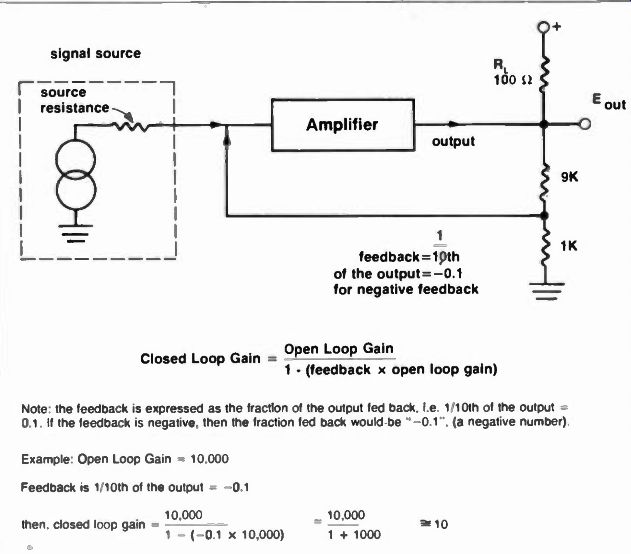
Fig. 1. The principles of inverse feedback.
Open Loop Gain Closed Loop Gain = 1 - (feedback x open loop gain)
Note the feedback is expressed as the fraction of the output fed back, i.e. 1/10th of the output 0.1. If the feedback is negative, then the fraction fed back would be ' -0.1". (a negative number)
Example:
Open Loop Gain 10.000
Feedback is 1 10th of the output = -0.1 10.000 then, closed loop gain = 1 - (-0.1 x 10,000) 1 - 1000 10
-------------
With an op amp the gain is determined by inverse feedback, and is almost completely independent of the gain of the integrated circuit itself.
If the op amp open loop gain changes 25%, the closed loop gain will show virtually no change! Thus changes due to aging, temperature, supply voltage, etc., have very little effect on the operation of circuits using Op-amps with feedback. This is the chief advantage of the op amp.
But, there are other advantages. Op-amps are less expensive than discrete amplifiers ... and they are much smaller and lighter. Over the years a great number of practical circuits based on Op-amps have been developed, covering almost every conceivable area of application. Some of these op amp applications were not really practical before the advent of Op-amps due to cost, size, etc. One such application is the "active filter," which enables us to build low pass, high pass, bandpass, and bandstop (notch) filters, down to frequencies as low as .01 Hertz! (Try doing that with LC filters). New thoughts about old circuits
Anyone who has used voltage regulators knows that the output voltage changes very little when the output current changes appreciably. If you think about it, the only way this can happen is if the voltage regulator has a very low internal resistance (source resistance). We therefore say, "A constant voltage source has a low internal impedance." (This concept will be important to you later on in this article). Similarly, a constant current regulator's output current changes very little, when the load resistance changes appreciably. The only way this can happen is if the internal resistance of the current regulator is very large. With a high internal resistance (source resistance), the source resistance will be much larger than the load resistance. The source resistance then limits the current, and the smaller load resistance has little effect on the output current.
Stated another way, in a series circuit consisting of one very large fixed resistor, and a much smaller variable resistor, the value of the smaller resistor will have very little effect on the current. The larger resistor is in effect, a "limiting" resistor. Thus a 1000 ohm variable resistor, in series with a one megohm fixed resistor, can change the current only one tenth of one percent! We can sum this up by saying, "A constant current supply has a very high internal resistance." (This will be important later in this article). Anything that tends to make the output of an amplifier a constant current source, raises the output impedance. Anything that tends to make the output of the amplifier a constant voltage source, lowers the output impedance. Keep this in mind.
Inverse feedback basics
Inverse (negative) feedback tends to make an amplifier's gain independent of the amplifier's characteristics, such as aging, drift with temperature, or changes with applied voltage. In addition, the feedback can be used to make the amplifier's output a constant voltage, or constant current. Negative feedback also changes the amplifier's bandwidth, distortion, and enables the gain of the amplifier to be precisely calculated in advance.
Remember that by making the output constant voltage, the output impedance is lowered ... but if we make the output constant current, the output impedance is raised! This is in contradiction to what you have read in many simplistic articles which almost always state, "negative feedback lowers the output impedance." Or, "An op-amp has an output impedance close to zero." Both of those statements are incorrect. The output impedance of an op amp is determined by whether the feedback tends to make the output look like a constant current source, or a constant voltage source. (Similarly, input impedance depends upon feedback being in the form of a voltage, or a current). Thus the way the feedback is implemented determines both the input and the output characteristics of the amplifier. If you think about that last sentence a bit, it will become quite obvious, since the feedback loop is taken from the amplifier's output, and fed back into the input.
Although we are discussing op-amps, the feedback theory presented will be useful wherever feedback is used. It is unfortunate that so little attention has been given to the theory and practice of feedback. Usually, one or two feedback formulas are given, without explanation ... as a result technicians must use them "blind" (without understanding). Feedback is a very powerful and basic tool, and should be well understood by technicians.
-----------------
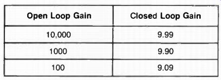
Fig. 2 The effect of open loop gain on closed loop gain.
Effect of changing open loop gain, with 10%, negative feedback
Open Loop Gain
Closed Loop Gain
10,000 9.99 1000 9.90 100 9.09
So long as the closed loop gain is much less than the open loop gain, changes in the open loop gain have negligible effect on the closed loop gain.
------------------
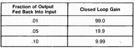
Fig. 3 The effect of changing the amount of negative feedback.
Amplifier Open Loop Gain is 10,000
Fraction of Output Fed Back Into Input Closed Loop Gain
.01 99.0
.05 19.9
.10 9.99
Note that the closed loop gain approximates the reciprocal of the fraction fed back. Thus if we feed back 1/100th of the output, the gain is 100. If we feed back 1/10th of the output, the gain is 10, etc.
----------------------
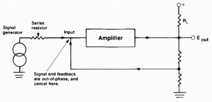
Fig. 4 Gain is reduced by signal cancellation at input of amplifier. This
often results in low input impedance. Signal at input is reduced to a very
low level. Input therefore looks like a very low impedance (near short), since
only a low impedance to ground could cause such a voltage drop across the series
resistor.
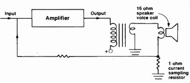
Fig. 5. Current proportional feedback. The output current is sampled by the
1 ohm resistor. The voltage drop across the resistor is fed back, out-of-phase,
into the input. This type of feedback tends to hold the output current constant.
(A constant current source.)
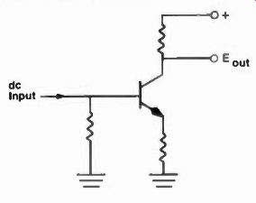
Fig. 6. A conventional transistor amplifier. Dc input level must be greater
than 0.5 volts to lust turn on amplifier, using a silicon transistor.
There is one point that must be made with regard to feedback ... feedback implies a "closed loop." The loop consists of the amplifier from input through to output, then back again from output to input through the feedback path, thus closing the loop.
If anything breaks this loop, the feedback system collapses. The reason for the word "anything" is not immediately obvious, so let's discuss it. Of course if we open the loop by means of a switch connected in series, you know that the loop will collapse . . . but there are other things besides a switch or a broken connection that can do exactly the same thing. If we overdrive a stage, to cutoff or saturation, the loop can no longer follow, and the same thing happens. Thus, in order for the feedback system to be operative, (as in any other analog system) you must be sure that none of the active devices in the loop are overdriven.
Figure 1 is the block diagram of an amplifier with negative feedback.
Beneath it is the formula for the gain with feedback. To use it you need to know two things ... the gain without feedback (open loop gain), and the fraction of the output signal fed back to the input. The closed loop gain will be less than the open loop gain, since negative feedback can only decrease the gain.
You must understand that the feedback does not change the gain of the amplifier itself. What happens is that the signal fed back into the input, from the feedback loop, is out of phase with the input signal, and the two signals tend to cancel ... therefore the input signal is reduced.
With an open loop gain of 100,000 (which is not unusual for Op-amps), a 200 microvolt input signal will result in a 20 volt output swing. This would be sufficient to drive the amplifier into saturation, using a 20 volt power supply! But, using negative feedback, we can drop the closed loop gain to 1000, and a ten millivolt signal will then result in 10 volts of low distortion output.
Notice that the input signal required is at a low level due to the high gain of the amplifier we are using. The actual signal at the input to the amplifier, is the output signal divided by the open loop gain! Remember, the feedback reduces the level of the input signal ... it does not reduce the gain of the amplifier.
In the case just mentioned, with a closed loop gain of 1000, and 10 volts of output, the input signal of ten millivolts is actually reduced to 100 microvolts by the feedback, illustrating the fact that the input signal with feedback must always be very small.
With this fact in mind let us examine the table in Figure 2, which has been made up with aid of the formula in Figure 1. Note that the gain of the amplifier with feedback is independent of the open loop gain of the amplifier, so long as the closed loop gain is much less than the open loop gain. (A big gain reduction). Figure 3 is a table which illustrates the fact that the closed loop gain depends only upon the amount of inverse feedback, and shows how the gain changes when the amount of feedback is changed.
Since the input signal is reduced by the feedback, you may be asking yourself how this can happen. For example, if we apply a signal of several volts from a previous stage, how does it become reduced to microvolts? Figure 4 shows a generator, connected to an amplifier with feedback. Note the use of a series resistor between the two. (If the generator has a high series internal resistance, the added resistor may be unnecessary.) If the signal is reduced to close to zero volts at the input to the amplifier, there must be a very low impedance at the input to the amplifier. This low impedance comes about because of the negative feedback into the input ... a fact which we mentioned earlier in this article. Pursuing this point further, the output of the amplifier is also a low impedance, because we are sampling the output voltage by means of the voltage divider ... and a change in output voltage causes a change in feedback voltage in such direction as to tend to restore the output voltage. Thus a change in loading has little effect on the output voltage, which is a constant voltage source, and therefore must be a low impedance! If we had taken the feedback voltage from a resistor in series with the load (a current sampling resistor) as in Figure 5, the feedback would tend to hold the output constant (a constant source) which is a high impedance output. By now you must be appreciating what was discussed earlier in this article about impedance changing! As a matter of fact, the ordinary emitter follower is a single stage amplifier, with close to 100% feedback. As a result, the gain is very low (close to one). Since the feedback is 100% of the voltage across the emitter load, which is directly fed back into the emitter, the output impedance is very low. You now are looking at the common emitter follower from the inverse feedback point of view! Now, back to Figure 4. It is often inconvenient to have an amplifier with a very low input impedance. To get around this, most op-amps use a differential amplifier, which has two inputs, out of phase with each other.
We can now use one input for inverse feedback, and the other input for the signal. Or we can tie one input to an unvarying source (ground, or a reference voltage) and feed both the inverse feedback and the signal into the other input. So far as the differential amplifier is concerned, THE INPUT IS THE DIFFERENCE BETWEEN THE TWO INPUT TERMINALS. This arrangement has some advantages. With an ordinary amplifier such as in Figure 6, the input voltage must be more than 0.6 volts dc if we are to go down to direct current (zero frequency). Many amplifiers must be capable of dc operation. With the differential amplifier shown in Figure 7, in a voltage regulator, there is very little difference between the two inputs, but the amplifier can handle a dc voltage differential input close to zero volts . . . which is essential in a voltage regulator.
Stated another way, the single input amplifier always has about a half volt offset (dc) at the input, since the input is between the emitter and the base, and the transistor requires a half volt of dc in order to turn on. (The differential amplifier input is between the two bases, and therefore can be close to zero). Further, the emitter/ base voltage changes with temperature, close to two millivolts per degree centigrade . If the transistor starts cold, and ends up hot ... or if the environment changes (as in automotive service) . . . the base/ emitter voltage can easily shift two tenths of a volt. This is a very large change (40 percent). The differential amplifier does not have this problem, since both sides of the amplifier change at closely the same rate, and therefore track each other, maintaining close to zero difference. Thus the differential amplifier is stable with temperature.
As a matter of fact the differential amplifier does not respond to anything that affects both sides of the amplifier equally. This is called "common mode rejection" ... therefore changes in power supply voltage have very little effect on the output. Since modern differential amplifiers are integrated circuits, in which both sides of the amplifier are made on the same chip, at the same time, of the same materials, in the same way, they are so closely alike that such op-amps and diff amps have great common mode rejection (CMR). Before the advent of ICs it was necessary to assemble these amplifiers from discrete components, which, of course, were not so well matched. As a result the IC op-amps and diff amps are superior to amps made of discrete components. In pre-IC years, good op-amps were quite expensive, due to the careful component matching required ... but matching is a natural result of IC fabrication, and the IC amps are not only good, but are also quite inexpensive.
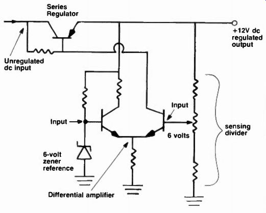
Fig. 7 A differential amplifier. The voltage input is the difference between
the two input terminals of the differential amplifier, and can be very close
to zero.
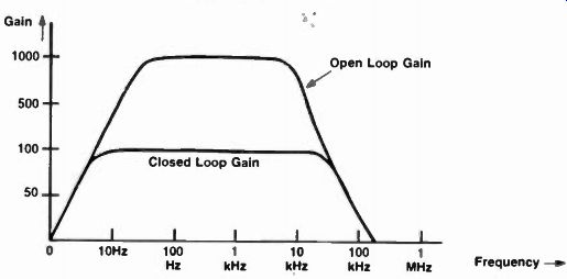
Fig. 8 The relationship of negative feedback and bandwidth. The bandwidth
increases as the closed loop gain decreases. Band width of amplifier, with,
and without, negative feedback
We mentioned earlier that negative feedback changes the bandwidth and the distortion in an amplifier. (Note that the word was "changes" and not "reduces"). Most texts merely state that negative feedback reduces distortion, and increases bandwidth, but this is not correct. It depends upon how the feedback is implemented, and what the feedback is intended to accomplish. For example, if we are using a frequency selective network in the feedback loop, in order to make an "active filter," we will actually increase the distortion, if we define distortion as a change in the shape of the waveform at the output of the amplifier, as compared to the waveform at the input of the amplifier.
If we feed a square wave into an active filter input, we may wind up with a sine wave at the output. This happens because a square wave is a fundamental plus odd harmonics, while a sine wave has no harmonics.
If the active filter is a good one, and is set to eliminate all frequencies higher than the fundamental (low pass), then a sine wave at the fundamental frequency will be the result. So you see that negative feedback does not necessarily "reduce distortion." It all depends on how we implement the feedback, and how we define "distortion." Similarly, negative feedback may actually reduce bandwidth, as in the case of an active filter. A better statement is, "If you apply feedback around an amplifier in such a way that the feedback loop maintains an 180 degree (out-of-phase) relationship with the input signal, and if the feedback loop has a flat frequency response, the feedback will increase the effective bandwidth of the amplifier, and reduce the distortion." Stated another way, "no phase shift, and a flat frequency characteristic." This tells us that the characteristics of the amplifier depend upon the characteristics of the feedback loop, so we have changed from an amplifier dependent upon the op amp's characteristics to one that depends upon the feedback loop's characteristics! We are now independent of the amplifier's drift, etc., but we need very stable components in the feedback loop. Do not expect low drift if you use composition resistors in the feedback loop ... they drift with time, temperature, humidity, etc. (especially in high values over 100,000 ohms). You must now use metal film resistors. Similarly you can't use ordinary disk capacitors intended for bypass applications. You will need to use high stability polystyrene or mica capacitors. And so it goes... This will all be very evident if you look at the tables in Figure 2 and Figure 3, which show that the gain of the amplifier is independent of the gain variation of the amplifier, and directly dependent upon the values of the resistors in the feedback loop.
For the moment, let us assume that you are using stable components in the feedback loop, and that the loop has good phase and frequency response. Then, and only then, is it true that the feedback will increase the bandwidth, and reduce the distortion. In the case of bandwidth, you can see how much the bandwidth is increased by referring to Figure 8, which shows the open loop frequency response curve of an amplifier with a gain of 1000. Superimposed upon it is the closed loop gain of 100. Notice that when we reduce the gain the bandwidth automatically increases! You can make your own graphical solutions in the same way.
Now, on to distortion. That turns out to be quite simple, since the effect of changes inside the amplifier are reduced by the same amount as the gain is reduced. Thus if an amplifier with 10 percent distortion has its gain reduced by a factor of ten, the distortion will also be reduced ten times, and becomes only 1 percent distortion! Simple, isn't it? The reason the distortion is reduced is that the input signal and the feedback are out of phase at the input to the amplifier, and thus tend to "cancel" each other. Distortion in the output is fed back out of phase to the input, but there is no signal component to reduce it (cancellation), thus the distortion fed back is quite large, and after going through the inverse feedback loop, literally is forced to "commit suicide" through the process of "non-cancellation." In a TV set, the video amplifier must handle not only the ac signal present, but also the dc (brightness level). If the dc level is lost, we need a dc restorer to restore it again. Similarly, in voltage regulators, the dc level must be amplified. In process control instrumentation, one volt may indicate a quarter of a tank full of chemicals, etc. Thus we often need an amplifier that goes down to dc. The op amp, or the diff amp, provide an easy way to handle these situations.
To come
In part II of this article, to follow, we will look at some practical differential amplifiers, and operational amplifiers ... how the feedback loop is implemented ... applications ... and troubleshooting procedures. In addition, an overview of the different types of operational amplifiers will be provided.
(source: Electronic Technician/Dealer)
Also see: Operational Amplifiers, Part 2