If you ever have wondered why an op amp circuit you were troubleshooting behaved as it did, you perhaps were not aware of some of the characteristics of the modern operational amplifiers; the text books don't always tell the whole story.
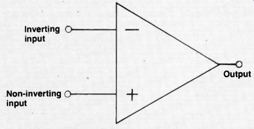
Fig. 1. The symbol for an operational amplifier. The + and - symbols identify
the two input terminals, as shown above. The actual input is the difference
in voltage between the two input terminals.
By Bernard B. Daien
In Part 1 of this article, we discussed the basic inverse feedback loop around a single input, single output amplifier, stating that feedback can change the input resistance, the output resistance, gain, distortion, and bandwidth of an amplifier. The differential amplifier was briefly mentioned, noting that diff amps have two inputs, and the input signal is the difference between the two inputs.
Common mode rejection was described, laying the groundwork for the integrated circuit op amp.
Before going further, it is important to reiterate that the diff amp input is the difference between the two inputs, and that anything that affects both sides of the diff amp equally does not produce a significant output signal.
Thus if both sides of the amplifier are subjected to power supply ripple, or if there is an unwanted signal pickup which is fed into both inputs, the output will not be affected. This characteristic is known as, "common Mode Rejection", i.e., anything common to both sides of the diff amp is rejected.
Now, on to the ... Basic Op Amp...
The basic op amp is a multi-stage amplifier, with a differential amplifier as the input stage, and a single output. It is so designed that one of the inputs is in phase with the output, and the other input is out of phase with the output, over the normal range of frequencies for which the op amp is specified. Usually with a high gain op amp, the open loop gain begins to drop off at 100 Hz or less! Most op amps have quite a bit of phase shift, due to the large number of stages involved, distributed capacitances, Miller Effect, etc. This phase shift prevents the output from being out of phase, or in phase, with the input, (depending upon which input is used), as the frequency is increased beyond a certain point ... and that may occur at a very low frequency! Since many data sheets fail to show the phase shift versus frequency, it is very easy to turn your "stable amplifier" into an oscillator, with "parasitic" oscillations at some high frequency by adding phase shift in the external feedback path.
Some amplifiers have a certain amount of compensation built into them, usually in the form of RC networks, which roll off the high frequency response in order to reduce the tendency towards self oscillation.
Other op-amps require that you use external components to achieve the same purpose. Stated another way, any time you close a feedback loop around a very high gain amplifier ... look out! The symbol for an op amp is shown in Figure 1, along with conventional terminal markings. The two inputs of the op-amp offer a tremendous advantage ... FLEXIBILITY. We can now use one for feedback, and the other for the signal, thus separating these two essential functions.
Furthermore, common mode rejection insulates these two from the influence of undesired factors, such as hum pickup, power supply voltage variations, supply ripple, etc. The op amp therefore becomes the closest thing to an ideal amplifier that we have. And, because it is flexible, its uses are limited only by our imagination! The op-amp can be used in so many different ways that the next part of this article will be devoted to op amp applications ... and that will only serve to scratch the surface.
This is a good time to clear up a little confusion about the difference between the op amp and a "comparator". The comparator uses the same symbol and labels as the op amp, and has two inputs and one output like an op amp... but the comparator is designed to be used open loop (no feedback). The reason for this is the comparator is not used as a linear amplifier. ... the output is in one of two states, high or low, much as in digital circuits. The state o the output depends upon whether the inverting, or the non-inverting input is the higher ... i.e., it "compares" the two inputs, and changes output state in accordance with whichever is the higher input.
Since the comparator is not intended for linear applications, (no closed loop) there is no danger of oscillation, and therefore no need for compensating capacitors. Since there are no compensating capacitors to charge and discharge, the output of the comparator can change state more rapidly than the op amp. This ability to change output quickly is called, "slew rate", and is usually given in volts per microsecond. The more voltage change per microsecond, the faster the slew rate.
So, if you are looking for speed, and linearity is not important, as in digital circuitry, use a comparator. If, on the other hand, you need linearity, or must use an inverse feedback loop for some reason, you will have to use an op amp, and live with a slower slew rate.
Operational amplifiers, like other amplifiers, have a large number of specifications, which must be consulted if you intend to use the amplifier for any practical purpose.
Some of these specs, and their implications are: "Output resistance" ... op-amps have an open loop output resistance that can vary anywhere from less than 100 ohms t several thousand ohms. Although this will be changed when the feedback loop is closed, nevertheless it is wise to choose an amplifier with a low output resistance if you intend to drive a low load resistance, while a high load resistance can be driven from either a high or a low output resistance. "Input resistance" ... again, if you are getting your input signal from a high impedance source it might be necessary to use a high input resistance op amp. Today we have amplifiers with Field Effect Transistors (MOSFETs) as the input stage, and these have input resistances so high, that for most purposes they look like an open circuit. In fact, op amps come in several families today, each with their own characteristics and advantages or disadvantages. Some are very fast, but have low input resistance, others work at very low supply voltage or current, etc. It is necessary to become familiar with, and study the specification sheets for the various op amps in common use... but be very careful, for nowhere else is "specmanship" so prevalent, (the practice of writing a spec in such a way that it appears better than it is, a la "used car dealer" style). "Input offset voltage"....the two inputs do not exactly track each other, due to minute differences in the op amp, therefore the inputs must be offset to bring the output voltage to the center of the output swing capability. It is possible to zero the op amp by changing the input biasing on one of the inputs, or by changing the characteristics of one of the input amplifiers by means of an "offset adjust" terminal provided on the op amp. Then there is "the input offset current"....op amps draw a minute input current from the signal source, due to the input resistance. The current in each input differs slightly, and if the source is a high impedance, this will cause a difference in the input voltages.
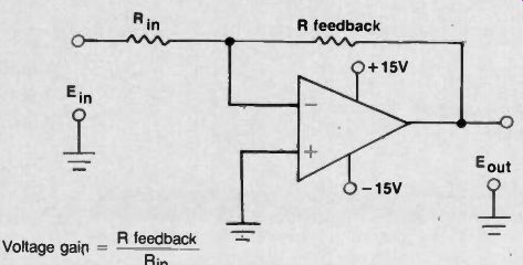
Fig. 2A. Inverting operational amplifier circuit.
(2A) Basic inverting circuit (for dual power supplies with common ground).
(Where Rin is the sum of the generator resistance and the resistor shown.)
Note: Input resistance = R_in in this circuit
Both the input offset voltage and current are temperature sensitive, and the better op amps are specified so that they change very little, while the less expensive op amps may not even have a published spec on input changes over the temperature range! Most good op amps have input currents in nano amperes, or, in the case of FET op amps, pico amperes, while the less expensive op amps may have input currents in microamperes.
Since the input current flows through the source resistance, and/or the bias resistors, if the two inputs are driven by different source resistances (or bias resistances), the input voltages will wind up being different due to the IA drops. Thus it is always good practice to make sure that both inputs of the op amp see closely the same resistances. Of course if the input current is very low, and the source resistances are also very low, the IR drops will be so low as to be negligible.
Finally, we come to a very important subject ... noise! Since op amps have very high gain, it takes very little noise in the input stage to produce very noticeable noise output.
Unfortunately, the subject of noise in op amps is usually treated with very difficult mathematical approaches. The facts are really quite simple ... op amps are like any other kind of amplifier, and generate noise in the same manner. ... but, to sum up, there are three basic kinds of consistent noise in semiconductor amplifiers. The first is a noise voltage, which depends upon resistance, temperature, and bandwidth, increasing as any of these factors increase. The second is noise current, which increases as the current through a semiconductor junction is increased, and also with bandwidth.
The third noise is called, "1/f" noise, (One over f noise) ... which means "one divided by the frequency" ... the mathematicians way of saying that the noise is inversely proportional to the frequency at which it is measured.
Stated another way ... the noise goes up as the frequency goes down! Thus, this noise is worst at very low frequencies, starting below one thousand cycles per second, and going on down to dc. This noise has never been fully understood, and is related to semiconductors.
There is another noise which is not consistent ... it consists of bursts of noise, and as seen on an oscilloscope, looks like corn popping ... and therefore has been dubbed "popcorn noise". This noise depends upon the processing used in making the semiconductors, and is generally lowest with the best quality processing.
Noise is very important, since in any system, the useable gain is limited by the noise. There are some simple tests for the different kinds of noise, and some things you can do to minimize noise. The noise voltage component can be determined by operating the amplifier with the input shorted. The noise current component can be found by operating the amplifier with the input fed from a very high source resistance (open circuit). Feedback does not affect the signal to noise ratio, since it reduces both the noise and the signal.
Also, as in other amplifiers, an impedance mismatch between the signal source and the input of the amplifier, can seriously degrade the noise performance. (This corresponds to a mismatch between the antenna and the input of a TV receiver.) The use of a bipolar input type of op amp will result in best noise performance for a source resistance under about 10,000 ohms, while FET input type of op amps do better above 10,000 ohms, and really shine at 100 kilohms and up. The reader might do well to refer to the June 1979 issue of ETD for a more specific discussion of noise in electronic circuits, if he wishes to pursue the subject further.
Now then ... what to do about noise. Since current noise is dependent upon current flowing through the semiconductors, reducing the current reduces the noise faster than it reduces the gain. Some op amps have a terminal which can be used to control the op amp's current.
Such amplifiers made by Fairchild are called "Programmable Op-Amps", by RCA "Operational Transconductance Amplifiers" and similarly by National Semiconductor.
As you will see later in this article, the "non-inverting" configuration (circuit) permits the feedback network to be fed into one input terminal, while the signal goes into the other terminal.
As a result, it is possible to avoid having the feedback resistor's value determined by the signal source resistance. This flexibility permits adjustment of the input resistance for optimum noise performance.
Therefore, the non-inverting circuit often results in superior noise performance when low signal levels are unavoidable. (This comment is often neglected in texts on op-amps). Of course, it goes without saying that bandwidth much in excess of that required will result in more noise. It has always amused the author to note the specifications on so called "high fidelity amplifiers" which go down to a few Hertz. With semiconductors there is a lot of 1/f noise below 40 Hertz, lots of turntable rumble, etc., ... and usually zero signal! It's like the 300 horsepower car on the city streets ... nowhere to use it. The practical moral is, "restrict the bandwidth if you want to reduce the noise". Communications technicians have long understood this simple fact, which is one of the reasons why communications receivers have very narrow bandwidths.
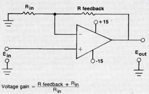
Fig. 2B. Non Inverting operational amplifier circuit. (2B) Basic non-inverting
circuit (for dual power supplies with common ground). Note: Input resistance
is very high in this circuit.
Current Differencing Amplifiers
There is another and newer member of the op amp families, which works on a somewhat different principle, and is intended for a somewhat different use. The original op amps were designed to operate right down to dc.
As a result they were intended to operate from dual supplies, usually about plus and minus 15 volts. The output of the op amp then was centered at zero volts, and could swing either positive or negative. But there was a continuing demand for an op amp that would operate from a single power supply, primarily to amplify ac signals. The conventional op amp came in a variety of types, and while some could operate from a single supply, the output swing did not go from nearly supply voltage right down close to zero volts.
The Current Differencing Amplifier (CDA) was designed specifically to operate from a single power supply, mainly for use with ac signals; its output swing can go from close to the supply voltage, down almost to zero.
There are some basic differences in the designs of the CDA and the older op amps. The op amps work on the difference in input voltage between the two input terminals, while the CDAs operate on the differences in currents fed into the two input terminals. CDAs have a lower input resistance than do conventional op amps, but they are quite inexpensive, and do the job they were intended to do. They are generally considered to be op amps ... the LM3900 quad op amps are one example of CDAs.
Just as there are many vacuum tubes and transistors which are basically similar, but are intended for different uses, so are many op amps optimized for specialized uses ... large output voltage swings, high voltage, low voltage, low power consumption, high speed, high input resistance, low output resistance, high power output, etc. Take your choice ... but choose carefully. An op amp is not an op amp, is not an op amp. You must know what your requirements are, find out what is available, then carefully study the spec sheets. If you can find a recommended circuit that does what you want, use it. Home brewed circuits may oscillate, have insufficient bandwidth, slow slew rate, etc. There are many pitfalls in which you can become entangled until you acquire a little experience with op amps. Op amps are not only simple to use ... they are deceptively simple to use! (A few resistors, and one IC., and "away we go... ")
Preamplifiers.
It is seldom mentioned that even a fairly inexpensive op amp can beat the performance of a very expensive op amp with the aid of a "preamplifier" specifically designed for this type of use. We are not discussing an audio type preamplifier, but rather an op-amp preamplifier.
National Semiconductor makes op amp preamps ... and I refer you to them for further literature on the subject, as it is beyond the scope of this article ... but you should be aware of their existence, in order to pursue the subject if you have need.
Current Boosters ...
Just as we can use a preamplifier ahead of an op amp, so can we use an amplifier following an op amp to increase the output current handling ability. This is especially useful in driving low impedance transmission lines, etc. It should be noted that the load for the op amp can be connected between the output terminal and ground, or between the output and the power supply line. In one case the current flows out of the output terminal, in the other case it flows into the output terminal! In op amp terminology we say, "the output can source, or sink, current." (If the current flows out of the output, it is a source. If the current flows into the output, it is a sink). Not all op amps are specified to both source or sink much current.
Some can source well but not sink.
Others, vice versa. Some do neither well, handling only small output currents ... and this is the reason why the current booster is required.
WHEN A CURRENT BOOSTER IS USED IT IS USUALLY INCLUDED IN THE FEEDBACK LOOP. Thus the closed loop is between the output of the current booster and the input of the op amp ... therefore the phase shift characteristics of the booster must be taken into account, for stability calculations. Literature usually does not make this point very clear.
By now you have probably realized that with op amps, preamps, and current boosters, the op amp family can do a very wide variety of tasks, from microvolt signals up through several watts of power, over a wide range of frequencies.
Op-amps are often used as a part of a system, rather than a "stand alone" device. They interface with some sort of signal source, and in turn, drive some other circuitry. Thus the use of preamps, and current boosters is a natural consequence to the way op amps are used. To consider the op amp as a stand alone device limits its usefulness in many applications. The use of an op amp as a differentiator, for example ... no one uses a differentiator alone ... usually it is as a "signal processor", shaping a waveform for sync use, etc.
The common idea that an op amp is primarily a "gain block" is therefore not very meaningful. In the next part of this article, dealing with applications, we will be using much of what we have discussed so far.
Basic Op Amp Circuits.
All op amp circuits fall into two main categories, "Inverting" or "Non Inverting", depending upon whether the input signal is fed into the inverting input, or the non inverting input. Of course the output must be fed back into the inverting input if we are to have negative feedback ... but, with the aid of a phase inverter, it is possible for the feedback loop to be fed into the noninverting input. It is all relative ... a matter of simple phase relationships.
Figure 2 illustrates the basic inverting, and non inverting circuits, along with the formulae for gain calculations. In these circuits the op amp is used as a straight amplifier ... the simplest of the various circuits.
These are the building blocks from which we can develop other more complex circuits later on.
Op amps have been around in integrated circuit form since the early 1960s. As a result, there are a lot of "surplus" older op amps available at very attractive prices ... but many of these are not bargains because they have problems ... odd power supply voltages, tendencies to "latch up", they burn up easily with overloads, can't handle a wide range of input signals or output swings, etc. It is wise to stay away from the following op amps for the above reasons: the 702 and 709 series. There are some fairly old op amps available in surplus that work well, and are easy to apply: the LM101, LM201, LM301, LM107, LM207, LM307 and the 741, 747, and 748 series, and you will find these satisfactory for most published circuits. By using cross reference lists available from Motorola, Texas Instrument, National Semiconductor etc., you can find DIRECT REPLACEMENTS for the above made by several manufacturers, with other identifying numbers.
You can buy op amps in single, dual, and quadruple packages. The dual and quads are especially convenient and economical when used for active filters, and signal processing, requiring several op amps. They also save quite a bit of space in compact equipment.
The next part in this series will discuss the practical considerations in using op amps, and several representative applications.
(source: Electronic Technician/Dealer)
Also see: Operational Amplifiers, Part 1