Alarm systems are not complex in concept; however, as a practical matter, installation may be quite difficult. Here are some of the techniques of selecting switches, running wires and installing foil tape and other hardware.
by John Sanger
Creativity is a desirable characteristic for an alarm installer. Every system that he installs presents new problems to be solved. And, just as no two systems are alike, no two installers will solve installation problems in the same manner.
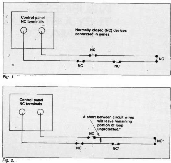
Fig. 1. Single ("Hot") Loop
Fig. 2. A short in a single loop
Mistakes, if we can learn from them, are valuable learning experiences.
Many of the following applications and techniques are based on personal experience from trial and error (with a few more errors than I sometimes care to admit): some are from veterans in the alarm industry who have shared their experiences with me over the years.
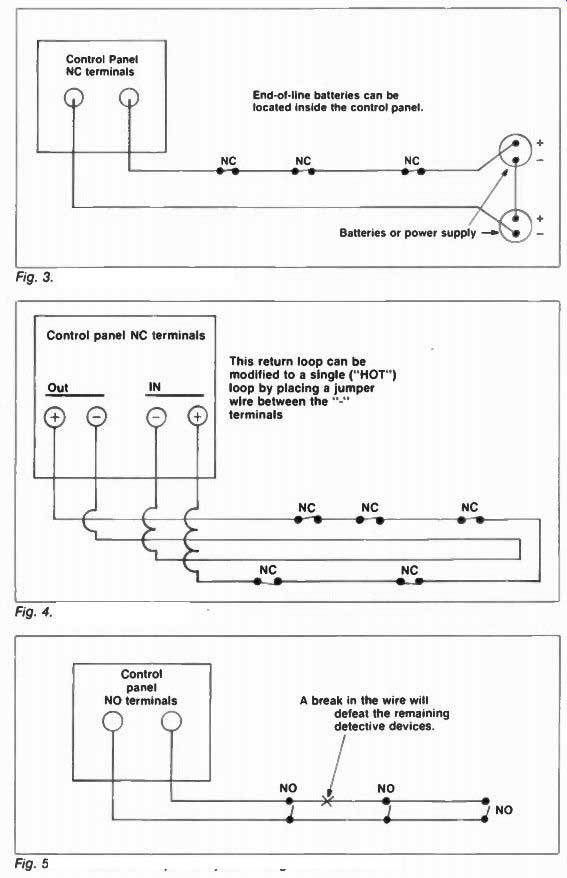
Fig. 3. An End-of-line power loop Control panel NC terminals
This return loop can be modified to a single ("HOT") loop by placing a jumper wire between the terminals

Fig. 4. The return loop A break in the wire will defeat the remaining detective
devices.

Fig. 5. The effect of an open in system using N 0 switches
Basics
It goes without saying that an installer should read the instructions that come with the alarm equipment.
Unfortunately, not all of them do and the results can be costly.
Following a few simple rules can save time, money, and needless headaches.
(1) Use good equipment. It will cost less in the long run.
(2) Apply the equipment properly.
Attempting to over-extend the capability of a piece of equipment will eventually cause problems.
(3) Make all connections before applying power.
(4) Double-check all connections before applying power.
(5) Be sure that primary power is derived from a 24-hour source and not from a switched ac outlet.
Protective Circuit: Loop Most burglar alarm circuits employ normally closed (NC) devices connected in series. Breaking (i.e., opening) the normally closed circuit will cause the control panel to go into an alarm condition.
There are three common normally closed burglary circuits: (1) Single-Loop (sometimes called a Hot Loop) (2) End-of-Line Power Loop (3) Return Loop The single-loop design is the simplest to install because it "dead ends" at the last sensor (Figure 1) and does not require a wire run back to the control panel. It should be noted, however, that a short between the circuit wires will render the remaining portion of the loop unprotected (Figure 2). The end-of-line power (Figure 3) and the return loop (Figure 4) circuits have true positive and negative voltage and polarity must be observed. Normally closed protective devices should be installed on the positive leg of the circuit. The single loop circuit generally has positive output and voltage cannot be checked because negative voltage is not present in the loop.
Some control panels offer normally open (NO) protective circuits as burglar alarm circuits-utilizing normally open devices connected in parallel. (Normally open circuits are most frequently used for fire, panic and hold-up devices.) Unless the system is designed to use an end-of line resistor for circuit supervision, a cut or break in the protective circuit wire will defeat all detectors beyond that point (Figure 5).
Magnetic Contact Switches
The most common detection device in a burglar alarm system is a magnetic contact switch. They are available in a variety of sizes, shapes and colors, and are available in normally closed and normally open configurations.
They are classified according to type of switch: either reed or mechanical.
The reed type is glass enclosed, making it suitable for corrosive or exposed environments; it is also more fragile than the mechanical type. Most of the modern switches, of either type, are very good -with some manufacturers rating the life of their switches at 10,000,000 cycles.
Whenever possible, especially in residential systems, recessed magnetic contact switches should be used. Not only do they enhance the appearance of the system because they are not visible, they reduce the possibility of tampering because they are not easily accessible. Long drill bits are available to facilitate drilling up through the door frame and header into the attic. While bits are available in lengths up to 72 inches, a 1/4 x 30 inch bit is usually sufficient.
If using magnetic contact switches on windows, a problem sometimes arises when the customer wants to open the windows for ventilation and have the alarm on at the same time.
Figure 6 shows one possible solution to the problem. A normally open switch can be used (because it is closed when it is away from the magnet) on the window frame and the magnet can be mounted on the sash.
Sliding the window past the switch will activate the alarm. A word of caution: if the window is left open past the switch when the system is armed there will be no protection.
Foil Tape
There is absolutely no substitute for experience when applying foil tape; the learning process can be frustrating.
Foil tape is one of the best protective devices available. There is nothing mechanical that can fail; either it is in one piece or it is not. Breaking the glass to which the tape is applied will break the tape as well. Foil tape, therefore, is simply a flat wire applied to glass.
Until an installer has had some experience applying foil tape, it is advisable to mark the outside of the glass with a felt-tipped pen or grease pencil to insure that the tape is applied in a straight line on the inside.
The foil should be applied 3-4 inches from the window frame, making certain that the bottom portion of the glass is covered since glass usually breaks in a downward direction (Figure 7).
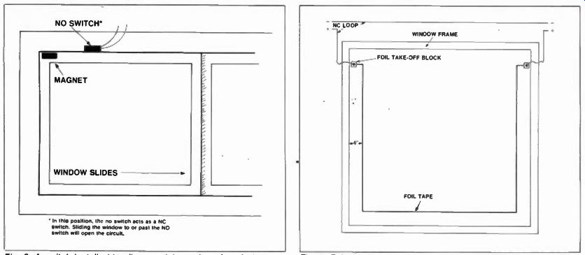
Fig. 6. A switch installed to allow partial opening of a window Fig. 7. Foil
installation on a window glass Fig. 8.
Foil corners
Make sure that the glass to which the tape is applied is clean. Then, if using self-adhesive foil tape, apply it using the line marked on the outside of the glass as a guide. If using regular (non-adhesive) foil tape, a coat of clear varnish 3/8" wide must be applied to the window. Once the varnish is "tacky," the tape can be applied and will adhere to the varnish.
Foil take-off blocks are applied to the glass where the foil tape ends and they are used to connect the tape to the wire loop. Several varieties of foil take-off blocks are available-and selection depends on specific application and personal preference.
Right angle turns with regular foil tape are made simply by folding the tape over itself. Square corner turns must be made with self-adhesive foil tape. To make a right angle turn with self-adhesive foil tape. make the standard turn in the opposite direction then fold the tape over itself in the direction that the foil tape is supposed to follow. A small amount of varnish in the fold of the tape will help hold the tape secure.
Glass Breakage Detectors
In lieu of using foil tape, glass breakage detectors may be used on windows. These detectors may be used successfully if they are adjusted properly--in strict adherence to the instructions provided by the manufacturer. Glass breakage detectors are well suited to residential applications where foil tape might not be desired from an appearance standpoint. They are more expensive than foil tape but installation labor is considerably less. (Note: vibration contacts should not be used on windows).
Zones
Even though the alarm system does not require zones. they can be useful if it becomes necessary to locate a problem. Toggle switches and or terminal strips inside the control box allow the troubleshooter to quickly isolate the problem zone --instead of individually checking each sensor in the entire system.
Wiring
Marking wires with tags or labels will save time if it is ever necessary to trace a wiring problem. Long wire runs should be marked periodically along the entire length of the run. When several wires are run together they should be marked. Simple markings such as NC DELAY (normally closed delay loop), NC INT (normally closed interior loop), NO PANIC (normally open panic circuit), or 12VDC PIR (12 vdc to passive infrared detector) are all that are needed -just enough for easy identification. Moreover, marking the end of each wire as it is dropped to terminate in the control box makes final hookup a simpler task. A variety of adhesive and tie type wire markers are available.
When running wires in an attic, staple them securely to the rafters or some out-of-the-way place. Keeping them out of harm's way will prevent accidental damage, and an unnecessary service call, because the customer snagged and broke a wire while rearranging the attic.
Periodically, along the run, leave some slack in the wire. Tapping into the loop to add sensors at a later date is easier if the wire is readily accessible and long enough to work with.
False Alarm Prevention
Entry warning devices should be used on control panels that have a pre alarm output during the entry time delay. An entry warning beeper (such as Moose Products' MA-2) or buzzer (such as Amseco's PAL328N) will sluice. The audible warning device reminds the customer to disarm the system before the entry delay expires -thus, reducing false alarms.
A side benefit is that the buzzing or beeping indicates to an intruder that something is about to happen.
Chances are that he will not stay to find out what happens next.
Summary
The practical side of alarm system installation--that is, what happens on the job site in the real world--must be learned, for the most part, from experience. However, common sense and planning are valuable assets to an installer and will pave the way for a smoother installation. Future articles will discuss specific applications of equipment and unusual techniques for solving installation problems.
(source: Electronic Technician/Dealer)
Also see: Alarm systems service (Oct. 1981)
Security insecurity--Legal considerations for the security business.