ET/D has, during the last year, attempted to give you a cross section of basic alarm system designs. In spite of their often simple appearance, trouble shooting can be confusing. Here are some common problems, diagnoses and solutions.
By Joe Lanier [President, Defensive Security, Jasper, TX, and the creator of Farley False.]
The first step in avoiding service calls is a proper installation.
Remember to always: Use good equipment (it costs less in the long run). Install it properly.
Read the installation and/or service instructions supplied.
Make all connections before applying power.
Double check connections before applying power.
If system will not "set up" (master control cannot be turned on without going into the alarm condition mode), you are in luck, as this is normally the simplest, and the most common service call. Generally, something out on the house protective closed circuit is open, such as a broken foil window tape, protected door left ajar, etc.
Supervised circuits
If system is of the truly supervised circuit type (both negative and positive protection circuit wiring) open the Master Control cabinet. If control has built-in or accessory power pak (or batteries) located inside its cabinet, you are starting the protective circuit at the control, and re-turning it to same (2 wires out, 2 wires back), after the building has in effect been "looped," catching sensors used.
Check circuit out terminals first for voltage. Placing your Volt-Ohm-Meter on low voltage dc scale across these terminals and reading proper circuit voltage output ( 3-6-12 vdc depending on control) will indicate this section of control is OK. Next, check the protective input terminals for voltage back in. Or, check these first if the system uses a circuit "tail-end power" design. No voltage in would indicate an open on the house circuit. Now go approximately to the center of the protective circuit and take another voltage reading across the house circuit. This will immediately show you if the problem is between you and the control output or input. In other words, you trace the good voltage until you lose it. The point of loss will be where the problem is, provided your problem to start with was an open condition, which is the most common.
Hot loop circuit
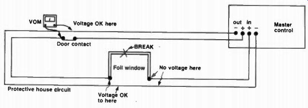
Fig. 1: A supervised, two wire out, 2 wire back circuit system.
Should your circuit be of the so-called hot loop type (a simple series circuit) which isn't generally recommended, you will have to disconnect the protective circuit from the Master Control terminals and check for continuity only across the 2 wires. You cannot check voltage (except voltage will appear across an open). Your VOM on continuity scale (normally Rx1) will register a short (needle swings all the way over), or close to it, depending on length/connections/resistance of the circuit, if circuit is good. However, we are still assuming your problem is out on the circuit, so the meter would indicate an open (no continuity). Now you will have to check the house circuit down the line for continuity. This can be a much longer process than voltage checking, especially on a large system.
Figure 2 shows a continuity only or hot loop circuit. If using 2 conductor wiring note that if a short (one side of the circuit touching the other side) occurred across these 2 wires, the circuit would only be good (protected) to that point. (Figure 3) Any switches beyond that point would be shorted out. Al though a single wire, out and back, well separated, would solve this potential problem, a broken wire itself could prove quite difficult to locate. Better overall security is provided by the supervised circuit.
Supervised preferred If the system utilizes 2 wires, one negative and one positive, a short would serve to rob your control input of required current flow to set up (Figure 4). Therefore, on a truly supervised circuit (both negative and positive used) a short would be evident.
2- Wire circuit with "E-O-L" Relatively new in the burglar alarm field is the 2-wire "E-O-L" panel design.
These controls start with 2 wires at the panel, but dead-end on a resistor (usually around 50 ohms). Therefore, the control would see the normal protective circuit resistance (generally 10-40 ohms) plus the end-of-line resistance. A short on the circuit (between the control and the end-of-line resistor) would cause the panel to fail to set up (or go into the alarm mode if armed), as the panel would see much less than normal resistance. This design is also sometimes used on a Normally Open Fire Circuit to provide supervision. Fire devices (such as pull stations, heat stats, smoke detectors) would be connected in parallel across the 2 circuit wires to short in event of an alarm. On burglary circuit applications, the devices (such as switches, motion detectors, etc.) would be inserted in series in the circuit. An opening by one of these devices would activate panel (Figure 5).
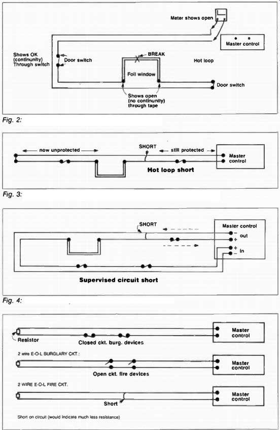
Fig. 2: A hot loop (a simple series circuit system).
Fig. 3: A short in a hot loop system disables the sensor beyond it.
Fig. 4: A short in a supervised circuit is evident.
Fig. 5: End-of-line resistor supervisor. A short causes an alarm condition.
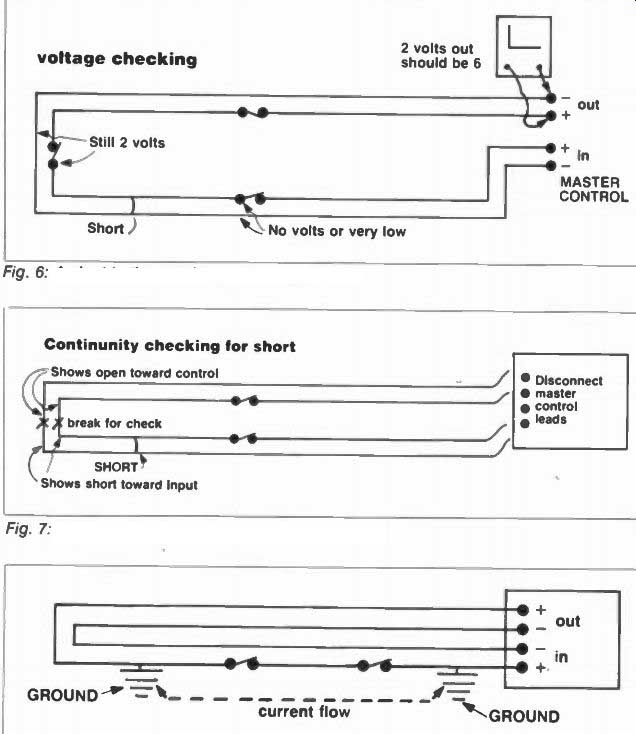
Fig. 6: A short in the usual supervised system.
Fig. 7: Short checking in a supervised system.
Fig. 8: Grounds in a supervised system. Since the circuit is floating one causes no problems, two will short out some part of the system.
Shorts
With a short present on the supervised circuit, the voltage reading will fall considerably below normal, between control power output and the short. Also, there will be little or no voltage reading between the short and the control input terminals (Figure 6). Therefore, if the voltage is much lower than it should be (example, 2v on a 6v control), disconnect the alarm circuit from the output terminals. Take another reading across the terminals, and if 6v are now present, you probably have a short out on the house circuit. Connect terminals back to power source and go approximately half-way down the protective circuit and disconnect it from the balance. Now take another reading across the 2 ends coming from the output. If good (normal voltage), a short exists between you and input terminals. If still low (or no voltage), the short is between you and output terminals. Continue in this manner until the exact location of the short is found. Shorts should be a relatively rare problem, if the system was carefully in stalled. A major source would be a staple, driven in, cutting insulation on the 2 conductors and shorting them.
Shorts may also be found by disconnecting the circuit from power terminals and the input terminals also. Make sure these leads are not touching each other on either end, and check continuity only with meter on Rx1 scale, on either end. Again, break circuit in approximately its center, and check both ways, running the short down in this manner (the same as you would have to on a hot loop type circuit). Remember to first remove power, and disconnect both ends, so you don't read back around and through the end connections (Figure 7). Continuity checking can also serve to indicate the overall condition of a house circuit. Twist one end of the circuit pair together (negative to positive) with NO POWER on the circuit. Check continuity across other loose ends on Rx1 scale. Resistance should probably not exceed approximately 30-40 ohms on average size protective circuit. A higher reading would be a good indication of poor connections. Also, watch needle on meter a few minutes to make certain it is remaining stable. If it is moving back and forth even slightly, it would serve as further proof of poor connection(s), as well as a possible swinger.
Swingers will be covered later.
Grounds
Another relatively rare problem on good installations would be grounds on the protective circuit. One ground would generally not affect system operation, but two grounds (Figure 8) would allow current flow to bypass some protected devices, rendering that portion of the circuit unprotected.
A ground occurring on both the negative and positive sides would have the same effect as a short. Make sure all connections and wiring are well insulated, with no bare wire or foil window tape touching any metal walls or frames.
Grounds may be located by meter on voltage (or continuity) checking from one side of circuit to a ground.
Swingers
A swinger is an intermittent, a momentary opening of the closed circuit, that recloses and does not remain in the open mode. The system has false activated, yet will reset. Needless to say, the circuit is "technically OK," at least for the present, otherwise the system would not reset. Let us say the circuit involved is a relatively simple tape wire switch circuit (perimeter circuit) with no motion detectors, beams, etc., involved.
First, make sure the master control is changing over to standby power upon failure of primary 110 vac power. Turn the system on with the protective circuit closed, and unplug the transformer, etc., for a few moments, then plug it back in. Should the system go into the alarm mode, this is probably the problem. The standby battery is either dead or too low to the power system, or not switching over properly. This would produce a non-power state during power failures, allowing protective circuit transistor or relay to fall out (become de energized), and be in the down or alarm state when power is returned to the unit.
If using tail-end power (such as dry cell batteries) make certain they are fresh.
Weak batteries may supply enough current to initially set up a control input, but not to maintain it. Remember, batteries cannot be properly checked with VOM meter or a voltage scale. Use a loading type battery tester.
Check overall resistance on the house circuit as earlier mentioned. Look for high resistance and or an unstable meter needle. Visually check the system, tightening connections along the way.
Especially check window foil tape for any tears or cracks. Remember, foil is metal, and will expand with heat and contract with cold. A fine, hair-line crack or razor cut may barely touch due to expansion when window is warm, yet contract enough to produce a false alarm when window area cools down during the night.
A VOM's meter is dampened, and may not spot an instantaneous open.
Special "swinger checkers" are avail able that are made especially for the alarm industry. They usually operate in this fashion: take power off the circuit, disconnect it from the control, and twist one end together. Connect the other end to the swinger checker, and go along circuit gently tapping on switches and glass areas protected by foil tape, pulling slightly on door cords, etc. A momentary opening of the circuit caused by this action will register on the checker by light and or buzzer, with lock-in output. Stop when this occurs and check close the area causing activation. If you do not locate fault visually, bring checker down to the suspected location and connect it directly across the window, etc., again setting up a vibration by tap ping area. If the checker activates, your problem is at or near this location. Possibly you have a broken wire inside a door cord, defective switch, poor foil connection under a take off block, etc.
Don't forget to check the tamper switches inside the bell or siren cabinet too.
These devices would be subject to out side environmental conditions.
If you do not have such a checker, and cannot locate trouble with a standard VOM, turn the system on, having first disconnected the bell output and placed a small horn or buzzer across these terminals. Now go down circuit tapping and pulling as above. The area having the swinger should activate the control, activating the buzzer. This is also a good method to double check yourself after having initially found and corrected what you felt was the problem. It is possible to have more than one swinger on the same circuit. Wire splices (if not soldered) can definitely be a problem area over a period of time.
All connections must be good and tight.
It is also possible, but only remotely, that outside RF is false tripping your master control. The protective circuit may be acting like an antenna, allowing RF to get into the master control panel board. This would be most likely caused by a strong, close by, transmitter, or a passing police vehicle. Again, this would be a rare situation. However, should it be the case, grounding of the master control chassis should solve it.
Should you suspect the problem is a defective master control itself, due to circuit checking good, etc., disconnect protective circuit and replace it with jumpers on the control terminal board, simulating a miniature house circuit. If the panel fails to set up with power applied, the control is apparently defective. Also, if the panel fails to activate when armed, when the jumper is removed, the alarm output mode is probably defective. If you are unable to make a field repair, such as cleaning and adjusting a relay, the panel will have to be replaced. Should the external bell or siren fail to sound upon alarm activation, don't automatically assume the panel is defective. Be sure and check bell or siren and disconnect its incoming wires and recheck. If no voltage is present, you have a broken (or possibly shorted) wire run. Of course if ± voltage is present here, the bell or siren speaker is apparently defective.
Now let's assume we have a more elaborate system. In addition to a perimeter circuit some form of motion detection is used. The protective circuit has passed all the swinger checks, and the master control is apparently functioning properly. ALWAYS check the perimeter circuit; just because the motion detector is more complex, don't assume it's the problem.
Troubleshooting time here could be saved by the use of a zoned control instrument with lock in alarm indication.
The perimeter circuit would be up one zone, with the motion detector on the other. Although more expensive zoned controls save time service wise by pin pointing the source of alarm.
Next month we will discuss the problems that some of the motion detectors can lead to and examine digital dialers and fire circuits.
(source: Electronic Technician/Dealer)
Also see: Next month