Here we examine some of the problems various intrusion sensors can cause and some ways to avoid them and look at dialer and direct wire system troubleshooting.
By Joe Lanier* [*President. Defensive Security. Jasper. TX. ]
This article is a continuation of Alarm System Service which appeared in October ET/D. It also presents a number of factors to be considered in the application of various intrusion detectors.
Study the motion detection check lists for possible false alarm causes (or mis applications). It is possible for the unit itself to be defective since anything electronic is subject to failure, but generally this is not the case if good, name brand equipment is employed. Most false alarms are the result of something happening within the detection field range. In some instances you may not be able to cure this condition with the existing form of detector used, and you may have to replace it with some other type of detector, not affected by the same conditions.
Should the alarm be only a very rare random condition, with no apparent explanation, a so-called "pulse counter" might be considered as a last resort.
These devices are inserted in the protective circuit between the control and motion detection unit. They may be adjusted time-wise for number of trips required, before the master itself would see an open on the circuit, for example, two trips within 10 seconds. This should serve to cancel out any one-time random alarms, yet alarm on continued movement within the protected area.
Motion detector malfunctions
--------------
Microwave application check list
Microwave motion detectors use very high frequency radio signals in the vicinity of 10 GHz. Air motion will not affect their operation. Antennas transmit the coverage in a controlled pattern (various patterns are available), which will penetrate most non-metallic surfaces, especially head on.
(1) A large loading door can be as large as 90-200 sq ft and due to its size can produce an alarm with as little as 1 /4 in. movement. It is advisable to parallel such doors, keeping the pattern off the doors.
(2) Microwaves can penetrate non-metallic walls and glass, mount the unit accordingly to avoid signal detection in unwanted areas, and adjust its range as required.
Note: Just because the signal does not catch a man-size target, does not mean it will not see a larger object. Walk-test outside of the building, including a vehicle drive-around.
(3) Microwave energy can be reflected by large metal objects placed or parked within range, into areas where coverage is not desired, resulting in false alarms.
(4) Fluorescent lighting is an ionized gas column that is reflective to microwaves, and can appear as a moving target. It is recommended that such lighting can be turned off during protected hours, or that the unit look over or under such lighting.
(5) Movement of pets, moving signs, blowing curtains, machinery in operation (such as moving fan blades), as well as water flow in plastic pipes (or pipes shaking) can produce alarms. A 1/4 in. wire mesh grill may be placed over fan blades to make them appear as a solid object to the microwaves.
(6) Make sure areas where protection is desired are not hidden by metal racks, bins, machinery, etc., which would block and reflect signals.
(7) Unit must be mounted on a firm, vibration-free surface.
(8) In event of RF problems, the unit chassis should be grounded, although this would be an extremely rare condition.
(9) Some manufacturers offer dummy load devices, which have impedance characteristics of an antenna. It will permit testing of the unit at full gain without sensing external disturbances or interferences, thus determining the status of the problem as to application or malfunction.
--------------
--------------
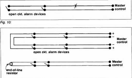
Fig. 10: A break in wiring to normally open sensors can render them inoperative.
Fig. 11: Typical supervised lire alarm circuits.
-----------------
Passive infrared application check list
Infrared detectors are optical and passive devices that monitor or receive infrared energy heat. They do not transmit. Thus, by not radiating energy they are somewhat less susceptible to false alarms than devices that transmit energy, but are generally higher in cost. The more expensive models generally provide range fingers (more than one such finger must be entered to provide alarm) along with logic circuitry. The devices are optical in that patterns are precisely defined (no range adjustment). They sense a change in IR radiation, such as caused by an intruder entering protected pattern.
(1) The target area should be temperature stable. Do not locate the unit in a direct draft of heating cooling vents. Normal operating temperature for IR's is - 20 degrees F to 140 degrees F. The unit will compensate for gradual changes in temperature, but a rapid change (such as 10 degrees within 4 seconds) can false activate.
(A) Mount unit at least 10 ft away from air outlet vents.
(B) Unit must not see an open flame, such as a fireplace.
(C) Avoid mountings where direct car headlights or sunlight would strike the optical viewer on the unit, through a window.
(D) An uncovered incandescent light bulb that burns out (or an ac power failure) will have an immediate temperature change that could create a false alarm.
(E) The unit should not view any subject to rapid temperature change.
(F) Small pets can emit through IA difference to false activate.
However, often the unit can be located with high mounting to allow pets to pass under the viewing area.
(G) Sensitivity is greatest for motion across the field of view, and is least for movement toward or away from the sensor. Performance is also determined in part, by background temperature and clothing type worn by the intruder, as well as high speed.
(2) Mount the unit on a firm, vibration-free surface.
(3) In the event of RF problems, ground the chassis of the unit.
Special note: In the remote event that outside RF signals appear to be false activating ANY TYPE of MOTION DETECTION unit (such as Ultrasonic. Microwave, Passive InfraRed) CONTACT FACTORY INVOLVED for recommended solutions. Test for outside RF activation by having police, etc., key their mikes near the building, etc.
------------------
These units are quite complex, rendering field service difficult. Most manufacturers would definitely prefer that you return the unit direct to the factory for repair. Be sure unit is properly used in the application, and that it is changing over to the standby battery provisions upon power failure. Most of these devices contain small gel cells or ni-cads, the average life span of which is approximately five years, and which may easily be field replaced.
Make sure the unit is plugged into (normally by a transformer) a live 24 hour 120vac outlet (master control as well), and is not being cut off at night by a breaker. This would result in a false alarm after standby power has beer exhausted, and is a very, very common cause of false alarms. Also, avoid USE of house circuits containing unusual items, which could create spikes on the line, such as time clocks. etc. If you suspect a recent lightning strike line surge change the transformer. It could be damaged, yet this is nearly impossible to tell with a MOM. Dialers Most dialers (tape) have a test position that tests most of the dialer's functions.
This pre-programmed taped message may be heard through a speaker in the unit, without actually dialing out. Test units also are available, which allow you to connect across the dialer phone line output, hear the ringing and the phone being answered at the programmed numbers (or a busy signal, etc.). In servicing this equipment, such a device (or headset) is almost required, to make sure you are obtaining a dial tone on the phone line you are connected to.
Make sure the dialer is actually being tripped (started), by your tripping device (such as bell output voltage or dry con tact closure), with dial tone present.
Tape contact head should be clean (spray cleaners are available). Should malfunctions exist, try a new tape (keep a spare tape programmed with your numbers, for testing purposes). Should the dialer itself be defective, replacement rather than attempting field ser vice would generally be called for. Dialers are fairly complex in operation and most manufacturers would prefer them to be returned for factory repair.
For digital dialers, special testers are available, with LED type digital read-out of the number being called, account numbers and violation code. Tip and Ring polarity must be observed if touch tone phones are in use.
Direct wire receiver systems
Most problems with direct wire systems (via leased telephone lines) are caused by the telephone lines themselves: opens, shorts, and grounds. Unfortunately, you usually have to literally prove to the telephone company that these conditions exist, before obtaining repair. The special "B.A. Circuit" is a dedicated private-pair, with nothing on the line but the voltage (normally 6 12vdc) from your master control, via a reversing relay. This voltage is terminated at the receiver, into the receiver itself. Voltage present, will be indicated by a normal meter reading. Very low, or no voltage or current would indicate trouble, whereas a reversal of polarity of the normal voltage would produce an alarm reading. A trouble reading will re main until the trouble is corrected, and an alarm reading will remain until the system is reset. In the latter instance, voltage polarity would revert to a normal, non-alarm state. The voltage itself is on the line 24 hours per day, regardless of when the master control is armed or off.
If a trouble condition is present, check for the line dc input voltage (and current) at the receiver location. Although rare, it is possible to have a proper voltage reading, yet no current reading, due to poor connections on the phone line it self. At least 10 ma should be present to properly operate the receiver. Also, check the voltage and current output at your master control prior to calling the phone company for service, to make sure your equipment is operational. At the receiver location be sure to unplug the receiver from the cabinet before taking the voltage and current readings directly from the phone line, so you don't read through the receiver under load.
When calling the phone company for service, it would help to have the test board (frame room) telephone number for the exchange you are in, and call them direct. State the B.A. Circuit Number if known, and the problem, such as "My equipment is putting 6vdc on line at (premises location), and we have n voltage at (receiver termination location)." The receiver meter power comes from the voltage you apply on the phone line from the protected premises. Power for the lamp and buzzer on the receive is provided by an accessory 6-vdc power pack (or batteries) at the receiver.
Special line amplification add-on modules are available to boost line voltage where needed for extremely long phone lines. Also, leased line monitors are available that parallel phone lines at the protected premises with a status LED type-light. This device will glow green as long as voltage is on the phone line, change to red for alarm, and be out in event of no voltage. It is inexpensive and can save service time, as you can call the subscriber to check its status rather than have to go to the location and check for phone line voltage.
Fire circuits & panic (hold-up) circuits
Fire circuits are generally Normally Open in design, and employ normally open detection devices that short (or close the circuit to activate the control. There fore, the devices used are installed parallel (across) the circuit. This holds true with the 24 hour Panic or Hold-Up circuit, which may either require a latching type device or momentary device to activate. A broken wire could defeat o render inactive the circuit, or at least a portion of it (figure 10).
Supervised fire circuits
These circuits are either 2-wire with a E-O-L (end-of-line) resistor used to provide supervision, or 4-wire (2 wires out and 2 back to control) (Figure 11). In the case of 2-wire circuits, the control could see an open circuit, such as a broken wire, because it couldn't see the resistance provided by the end-of-line resistor. The 4-wire would also see a open, due to a loss of voltage. A short on either system would provide a alarm condition. Four wire is known a "Class A," and 2-wire as "Class B- wiring. Troubleshooting would consist o using a VOM to trace an open (no continuity) or short (causing a constant alarm condition) when the system is armed. Tracing shorts was covered earlier. Just keep in mind that Fire and Hold-Up circuits operate open circuit, with alarm devices that close the circuit to activate. Burglary circuits are generally closed circuit, with alarm devices that open the circuit, requiring for series wiring, rather than parallel wiring.
--------------
Ultrasonic application check list Ultrasonic is "silent sound," inaudible high frequency sound waves. Any movement within the protected area changes the pattern of the waves.
Flood coverage is generally provided within adjusted range, but it does not penetrate walls, etc. Maximum range listed by the manufacturer is often based on a temperature of 75 degrees F. with 40% relative humidity, with satisfactory operation normally rendered between 50-90 degrees. Lower temperatures will reduce the range up to 20% at 20 degrees, but humidity will generally affect range only about to 10%, average range of most mini-sonics is 20 ft \ 25 ft maximum. Larger multi-head systems may be used to provide trap zone coverage in additional areas with various protection patterns offered. Hard, reflective surfaces allow for greater coverage per area than soft absorbent areas with carpet, drapes, etc.
(1) Ultrasonic signals are blocked by merchandise, cartons, etc., stacked too near transceivers. This can result in false alarms due to excessive wave reflection (unit too hot), as well as blocking the area coverage is desired in. Units generally should not be mounted over 12 ft from the floor.
(2) Setting the range control too high (unit super sensitive) can result in false alarms. Adjust sensitivity no higher than required to provide coverage desired in protected area.
(3) Excessive air turbulence can false activate the system. Mount unit(s) at least 10 ft away from outlet vents, loose fitting, drafty doors, etc.
(4) Harmonics within the frequency range of the system can cause activation. This can be caused by mounting too near telephones, TV or Hi-Fi equipment, and any equipment powered under air or gas pressure, such as leaking compressors. Also, excessively strong outside RF signals (unit chassis should be grounded) can cause trouble. Harmonic problems also can result from rain on an uninsulated metal roof.
(5) Movement in the protected area by pets as well as air movement of signs, curtains, etc., can cause unwanted alarms.
(6) Unit must be mounted on a firm, vibration free surface, not subject to vibration from passing trains, traffic, etc.
(7) Remote slave units generally require shielded cable to avoid inductive pickup. This wiring should be kept away from existing ac premises wiring at least 1 ft and should cross at right angles only.
(8) If more than .one, single stand alone mini-sonic is "installed at the same location, they must be of the crystal controlled type to avoid cross talk (inter-reaction false alarms). (9) Doppler Meters (testers) are available, and should be used on the large systems to check over all stability and system balance.
------
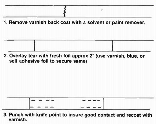
Fig. 12: How to repair window foil.
1. Remove varnish back coat with a solvent or paint remover.
2. Overlay tear with fresh foil approx 2" (use varnish, blue, or self adhesive foil to secure same)
3. Punch with knife point to insure good contact and recoat with varnish.
(source: Electronic Technician/Dealer)