Look around any area not dominated by cable and you will see infinite possibilities for improved television reception through new, adequate, properly installed television antennas.
By Stan Prentiss
IT'S TOUGH to see a picture when no picture exists. Weathered and broken transmission lines with large standing wave ratios, poor quality, cracked plastic, and improper matching impedances, all immersed in the dampness of a wet, shingled roof or flooded gutter characterized much of America's consumer receiving apparatus.
Coupled with inadequate, outmoded, soot or salt spray-encrusted antennas of either ancient vintage or with defective/broken elements, you then have a slightly exaggerated but basically realistic picture of what's atop 20-odd million U.S. rooftops today.
That it's time for a change, will be disputed by few, but by whom, what, and where are all mostly intangible questions with which the average homeowner is unprepared to deal, since the many fulltime installation crews often can't answer them either. Unfortunately, cheap antennas and lower grades of transmission lines are where many installers make their money, and usually mediocre or poor TV pictures result.
However, with the advent of new, broadband receivers, many newer transmitting facilities, the spread of CATV, and even new TV stations on the air, decent sets require maximum signal quality for worthwhile pictures.
Transmission Lines.
The least understood of our two prime topics is lead-in (cable) or, in more elegant terms, transmission lines. In television there are two main types: twin (or bright) lead, with 300 ohms impedance and two stranded conductors; or coaxial (a cable within a cable) cable, having 75 ohms impedance and a single center conductor.
Unshielded twin lead, before the relatively recent advent of first quality coax, was almost universally used in most home-type TV installations.
Shielded twin lead is very lossy and isn't used in routine installations.
In the early days of television when there were only one or two TV stations serving each community and pictures over the air were a great novelty, almost any sort of image on the tube was relatively acceptable. Today, 15 TV stations in a 40-mile radius aren't novelties any more, and the FCC is already indicating it intends to add more soon in some of the larger markets barring over whelming opposition. Meanwhile, in the intervening 30-odd years, telephone and electric lines, 2-way radio, citizens band radio, and am/fm radio stations of all descriptions have all increased enormously in numbers, and this means more interference to all types of signals.
In addition, stray signal pickup from spark-emitting lawnmowers, trucks, and even some automobiles is still prevalent in many communities. The time's come, therefore to go almost 100-percent with coaxial cable.
But simple basket weave, open spaced loose shielding is insufficient for the job, and an aluminum wrap around the polyethylene center insulator plus closely braided outer shielding and vinyl wrapping against the elements are strongly recommended. This will ensure minimum outside signal pickup and best signal transmission between antenna and receiver, especially for ultra high TV frequencies at 470-890 MHz. Then with good signal propagation characteristics, not too much capacity, and modest signal attenuation per 100 ft., the use of coax turns into a real bonanza that will outlast ordinary twin lead by many years and still retain most or all of its signal passage and shielding properties. In the long run, the combination of cost and prolonged utility is actually cheaper than ordinary or even extraordinary twin lead.
As an illustration (Fig. 1), we'll use a 6/U cable type that's 100 percent sweep tested and fully characterized by Belden Corp. This particular coax., numbered 9114/9116 (40 or 60 percent braid cover), is available to distributors (who can cut shorter pieces) in 500 and 1,000 ft. lengths. From right to left you see a steel, copper-clad center conductor then the core, aluminum wrap (Duobond), tight braid wrap, then the covering vinyl jacket. All characteristics, of course, are interesting, but especially note the 78 percent velocity of propagation, the 18 AWG center conductor specification, shield coverage, and the very small dB attenuation per 100 ft. between 50 and 900 MHz-the entire fm and tv band.
Note also that the cable has been electronically swept between 5 and 300 MHz to check for any electrical discontinuities. This way your are assured of obtaining first class cable that can be used in MAN, CATV, or the better home installations.
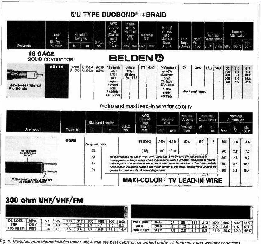
Fig. 1. Manufacturers characteristics tables show that the best cable is not
perfect under all frequency and weather conditions. 6/U TYPE DUOBOND + BRAID
; 300 ohm UHF/VHF/FM
Now compare statistics with Belden's best all-weather twin lead and you'll notice only a two percent increase in propagation velocity, very little difference in attenuation--actually less in coax through 200 MHz-and a third less capacitance which makes little difference in relatively short hauls of coax. And toward the end of the maxi-color table see what the manufacturer's recommendations are in this excellent twin lead's usage.
Is it really worthwhile continuing the use of run-of-the-mill twin lead that, when old, dirty, and wet, actually retains only a few percent of its original signal handling ability? Most people would obviously say "no!" First because a lower impedance cable (300 vs 75 ohms) means a better antenna/receiver match, therefore little or no standing waves, exclusion of outside interference, the entire incoming signal contained within the cable itself, and a small diameter lead in that can be taped to the antenna mast, installed with a staple gun, draped over air conditioning ducts or any other metal, and easily brought into housing without awkward and expensive insulators. And if you're some distance away from the tv transmitter or want several receivers connected to the same antenna, highly satisfactory uhf/vhf amplifiers are available for a reasonable price (about $50 to $75) that will distribute excellent signals throughout the house or apartment, permitting shielded splitters or couplers to serve the entire dwelling or working area.
If you're still not convinced, look at the characteristics of some ordinary twin lead just below the deluxe twin cable that is Belden's best. You pay less, but the price is proportionately costly. Especially note the difference between dry and wet. Some of these figures, as you can see are rough! We could continue and carry these analogies to extremes, but the results wouldn't change; good coaxial cable, in almost every conceivable way, is vastly superior.
You may also be interested to know that caution is suggested when using "F" connectors with poor quality coax.
Loose shielding often does not make good contact, especially with loose braid, which then results in a 30 dB loss through leakage. And one piece "F" fit tings make better cable contact than the two piece versions since they're safer, stronger, and have less leakage.
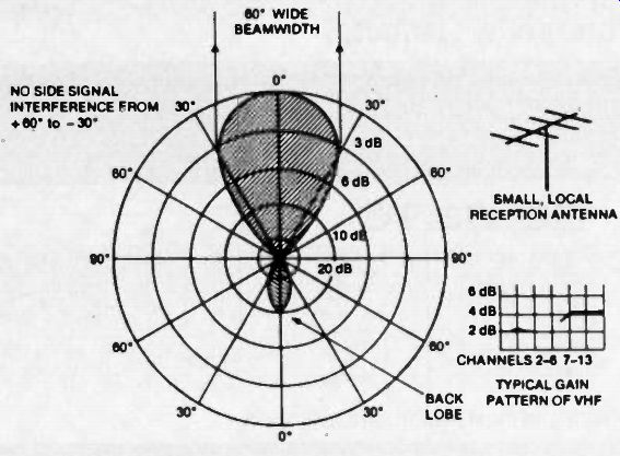
Fig. 2. A typical local antenna polar pattern and gain diagrams. Front-to-back
ratio 10:1 (poor).
Antennas
Evaluation of these highly specialized transducers designed to pick up broad cast electromagnetic radiation and de liver it in the form of microvolts or millivolts to some receiver's antenna terminals isn't really much more difficult than transmission lines. Just like cable, however, you must look at the specifications and understand what's needed, where, and why. Unfortunately, just any old antenna stuck on some roof out cropping won't do. Smart installers select a certain antenna for a specific application, use good cable downlead and make sure few, if any, standing waves interfere.

Fig. 3. Jerrold's 10 to 90-mile super VU-Finder log periodic. Most elements
are driven, not parasitic. SUPER VU-FINDER Model VU-934S
For suburban to fringe reception areas.
Every antenna has both ISWR or VSWR (current or voltage standing wave ratio), and front-to-back ratio characteristics built in. And if the manufacturer is on the beam, you'll also be able to see the various channel beamwidth, plus uhf/vhf gains (with reference to some isotropic or mythical dipole), and the antenna's overall signal handling ability called polar patterns. In some in stances, channels 7 through 13 (high vhf) may require medium or high gain; in other situations, uhf is the critical factor. So, for best reception, you'll have to design your particular installation to accommodate one or more special ad vantages or problems. Here's how: Standing wave ratios usually amount to E(max)/E(min) or 1(max)/1(min) and can be thought of as incident (outgoing) or reflected (incoming) waves which combine to form peaks or valleys of stationary energy, either adding to or subtracting from the received signal. This usually means signal loss and even undesirable fine line picture interference.
Half and quarter wave traps are often used to remote this difficulty, but a good impedance match between antenna, transmission line, and receiver generally solves the problem. Here is where nominally low impedance 75-ohm cable has less chance of producing standing waves than 300-ohm twin lead. And if you're using 75-to-300-ohm balanced to-unbalanced transformers (baluns)
both at the antenna and receiver, it's very difficult, especially with coax. to generate SWR unless there's either faulty antenna or cable. Some antenna companies, such as Winegard, are even providing 75 to 300-ohms switch terminations at antenna-cable couplings for automatic impedance matches to down leads. And when the TV makers finally discover there's only 1.3 to 1.5 dB loss difference at 900 MHz between the best twin lead and coax, perhaps we'll even have all-coax. u/v splitters going into at least the better receivers instead of the usual awkward combi nation of the two. Usable signals from uhf stations are equivalent to vhf any way, and since there's a minimum insertion loss of from 0.5 to 1 dB among even the best baluns, why not use good quality coax. for both? Furthermore, u/v tuners are annually becoming more comparable in signal pickup.
The next points worth making involve front-to-back antenna ratios, along with side and back lobes, plus beamwidth.
These are all important considerations since they directly involve antenna selections for metropolitan and distance areas and the actual station spread you want the antenna to "see." Let's draw a pattern of some hypothetical metro antenna (Fig. 2) with a good, wide front lobe, no side lobes, and a fairly prominent back lobe. This would be almost ideal for any short-to-medium distance antenna if was not for the 10 dB back lobe. Usual interferences between + 70 and - 30 degrees aren't going to penetrate normal reception frequencies since they're tuned out. Because of the 10 dB back lobe, however, this antenna's front-to-back ratio is 10:1, and you'd much prefer a 20:1 situation to prevent co-channel and other interference from entering.
Unfortunately, low gain antennas with broad beamwidths are going to exhibit some back or side lobes, and this makes very little difference in high signal areas that are not surrounded by large buildings or highly uneven terrain.
But when such phenomena do occur, you'll need a high gain antenna with considerable directivity (narrow beam width), then reduce its signal pull with resistive padders called attenuators.
Unfortunately, all input signals are equally attenuated by this method and if a single broadcaster is your only problem, you may require an especially cut transducer for that one particular station-a situation which can be arranged if you're willing to pay custom costs. On the other hand, judicious selection of a combined u/v antenna with suitable gains can probably solve most difficulties without either undesirable attenuators or peculiar transducer rigs. We suggest the latter approach, but you'll probably need to investigate more than one manufacturer's offerings to find the particular product.
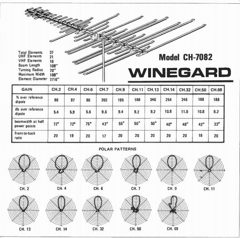
Fig. 4. Winegard's 10 to 40-mile antenna with a full set of polar patterns
and other data for each channel. Model CH-7082 WINEGARD
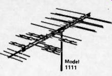
Fig. 5. Typical Channel Master Quantum antenna high and low channel polar
pattern.
What about stations in more or less opposite directions? Well, we're situated in something of a modest Vee between two large cities, and a single u/v rig does moderately well for both. A rotor, of course, would help, but those things sometimes freeze, lock up, or have connection problems that either require the services of a mechanic or early replacement . . . Use at your own discretion.
Now let's proceed to the very real world of antennas, polar patterns and gains for first-hand observation of what's new and worthwhile in the market. As you may or may not know, plain antennas don't even have unity (1) gain, therefore all their statistics come from comparisons with a mythical dipole, whatever that is. Nonetheless, comparing antenna gains is not necessarily odious, nor do we flinch from comparing some of the better arrays now on the market. At the moment, some of the best designed and best selling antennas are made by three manufacturers: Taco-Jerrold, Winegard, and Channel Master. True, these are three of the more expensive signal receptors, but their overall performance is well worth the difference.
Taco-Jerrold (Fig. 3), a true log periodic, has mostly driven elements, a few directors in front and no reflectors for the usual rear isolation since a coupling harness changes phase between front and back so that the two extremes are 180 degrees out-of-phase. This, of course, serves as an electronic rear reflector and generally prevents back reception of unwanted signals.
Careful phasing and sufficient elements offer good broadband, high gain, and a highly effective antenna array that easily includes uhf at considerable signal gain in the front end u/v coupling.
The price is somewhat steep, but if you want the best of all worlds with maximum efficiency, a good log periodic will do the job nicely. Our test antenna is a model VU-934S, having an element count of 37 (including a half dozen directors), a bow-tie uhf arrangement with corner reflector, followed by all the tuned vhf elements. On low vhf, note the very broadband beamwidth for channels 2 through 6, somewhat less for 7 through 13, and a very similar composite pattern for uhf stations 14 through 69-channels 70 and above are now FCC-assigned to land mobile, although a few remain in the use as tv repeaters.
Gain for low band channels averages better than 5.5 dB, high-band channels over 10 dB, and uhf (solid line) about the same. Larger models have double booms for maximum strength, and VSWR, according to Jerrold does not exceed 1.8:1 for vhf or 1.5:1 for uhf.
Breakaway elements extend these ranges to a full 890 MHz for all-channel uhf, and maximum fm reception, as well.
Front-to-back ratios are between 18 and 20 dB, and the VU-934S is quite useful between 10 and 40 miles from stations in reasonable reception areas, and all elements have an alodine finish against weather and corrosion.
Winegard (Fig. 4) is offering a special line of Chromstar antennas with a recent tri-linear uhf system that performs as three half wave directors at the high end and becomes a simple half wave director on the low end, resulting in relatively linear gain for all uhf channels.
Elements are cross-phased and end fire driven in an overall high performance, ruggedized Yagi. And since this antenna has no corner reflector and a relatively flat plane, there is little wind resistance.
Truss-type phasing bars top and bottom offer maximum signal transfer and 7/16-inch diameter aluminum elements give greater strength and somewhat better performance than smaller tubing.
But the feature we like best in this line is a weather-protected cartridge housing with built-in balun for either 75- or 300-ohm downlead connections. This antenna, as you will observe, is quite comparable to the 37-element Jerrold except a little difference in the upper vhf channels, according to the gain pat terns, but my own tests showed this not to be true. U/v pickups were almost equal. Even most front-to-back ratios are equivalent. Some back and side lobes do show on channels 4, 7, 50, and 69, but are well controlled and shouldn't be a problem since the minimum front to-back ratio for all these channels is 17, with the remainder around 20. Beamwidth is very broad among the low vhf channels, and respectable among the high vhf stations. Uhf is about what you'd expect, considering the frequencies. Since this is another 37-element receptor, its useful range lies between 10 and 40 miles as the crow flies.
Channel Master's perhaps most effective antennas in problem locations (they make several other types) is its Quantum Series. These were designed for sharp beam patterns and exceptional front to back ratios (up to 35dB) as well as excellent mechanical strength.
Available in UHF/VHF and VHF only versions, various Quantum antenna models are suitable for from suburban to deep fringe use, the longest, the Model 1110 being almost sixteen feet in length. The Quantum series has been used to solve severe reflection problems in city and suburban locations as well as receive stations up to 150 miles away with stations about 45 miles away off the back.
Other features of the Quantum series are a full line of baluns and preamplifiers, housed in a compartment in the antenna structure, double boom construction, and 3/8 in. bolts for mounting.
Typical beam patterns and front to back ratios are shown in Figure 5.
Suggested retail prices on all antennas illustrated for the three manufacturers range from $35 and to over $100, depending on the number of elements and your sources or installer. Installation, of course, is extra, and overall prices vary with lead-in, technical skills, and geographical location.
Part 2 of this series will discuss indoor antennas and how they're being aided by broadcasters transmitting circular polarized patterns, and an up-to-date rundown on CP itself.
(source: Electronic Technician/Dealer)
Also see: TV Antennas, part II--Circular polarization and indoor antennas