A WORLD WITHOUT AVC--Automatic Volume Control--would be filled with fractured audio and video. Explanation is that AVC is the steadying force in receivers of most every description from tiny AM portables to communications receivers, TV sets, and just about everything else that breathes in a signal.
Remove AVC from your table radio and it would probably break up on local stations. Take it out of your TV set and color might scramble and spill through the image-or pictures turn negative because of signal overload.
Blast It. It's been said that AVC "makes strong signals weak and weak signals strong." That simple definition goes back to AVC's original objective of reducing "speaker. blasting." The phrase is perfectly descriptive because an uncontrolled receiver produces excessively loud sounds in the speaker while receiving strong signals. You could adjust the radio's volume control by hand, but imagine doing it in an automobile while driving. Your hand might never leave the volume control! This is where AVC comes to the rescue. It senses the wavering signal, develops a control voltage in proportion to that signal, then applies it as a continuous correction. It also cures a problem that no amount of volume-control fiddling can cure. It's an overload condition where strong signals drive the receiver's early stages into highly distorted operation, resulting in mushy, unintelligible audio in the speaker.
Though a car in motion is one cause of fluctuating signals, there are others.
Atmospheric fading due to changes in the ionosphere has a tremendous effect on the strength of shortwave (3 to 30 MHz) stations. At higher frequencies (VHF and UHF-TV, for example), passing vehicles, changes in tree foliage, and even moisture content in the air vary the number of microvolts induced in an antenna by a distant transmitter.
In all of these cases, an AVC circuit attempts to compress or expand the signal into some mid-range or average value. As you might suspect, AVC can't recover a signal deeply submerged in atmospheric noise and make it readable.
Nor can it clean the snow from a faraway TV station arriving in a remote fringe area. But it is capable of some pretty miraculous stunts, as we'll see shortly.
The AVC Idea. Almost every AVC circuit follows a similar general route.
First, it taps into the receiver circuit at some point to sample a bit of the incoming signal. The sample provides information on the relative strength of the arriving station. Next, the sampled signal is processed into a form which enables it to control the radio-frequency amplification of the receiver. This becomes the AVC control voltage and it's fed back to some earlier point in the receiver.
If a powerful station is being received, it produces a high AVC voltage, which reduces the receiver's ability to amplify. Upon receipt of a weak signal, little AVC voltage develops, so the receiver runs at high amplification.
From Carrier to Control. The overall idea appears in Fig. 1. We've shown a standard broadcast station transmitting a signal whose carrier is increasing from weak to strong in three steps. Note that the carrier is assumed to be originating from the station at three fixed levels, with no audio modulation at this time.
(Audio causes a complication we'll get to in a moment.) The changing carrier signal enters the receiver antenna and proceeds through RF and IF stages until it reaches the diode detector. Since the alternating carrier can go through the diode in one direction only, it's rectified so only the negative portion appears at the resistor forming the diode load. The AVC signal, however, is still hidden within the rectified carrier, as shown by the dotted line. This means that it must be processed further before it becomes a suitable control signal-a DC voltage which varies in step with carrier strength.
This is where the problem of audio modulation (voice or music on the carrier) complicates AVC development.
The trouble is that intelligence on the carrier is AM, or amplitude modulation, which is electrically similar to the changing carrier strength AVC will attempt to fight. It would hardly be suitable if AVC attacked loudness changes in the program, rather than average changes in carrier signal. Fortunately, it's possible to fashion a filter which ignores audio in the sampled carrier.
As shown in Fig. 1, there's an AVC filter comprised of a resistor and capacitor. In a typical tube circuit these values are a few megohms for the resistor and about .05 uF for the capacitor.
They form a filter which responds at the rate of about 0.1 second (its time constant). This interval of time has been carefully selected to fulfill certain boundaries of AVC operation.
First, the filter must remove any audio modulation from the sampled portion of carrier. Since audio variations occur much faster than 0.1 second (the lowest audio tone is about 20 times per second), the filter smooths out any audio in the AVC circuit. Yet, the AVC filter must not respond too slowly.
When driving in a car, for example, you might receive a fluttering signal and need fast-acting AVC to exercise quick control.
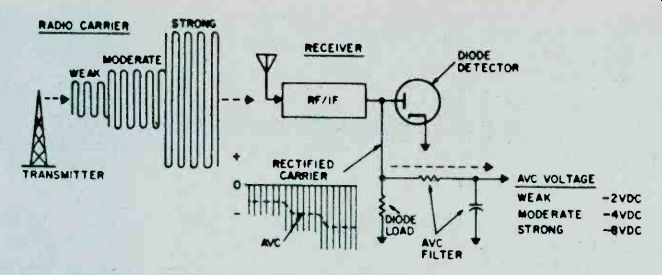
Fig. 1. Diode detector develops AVC voltage in typical tube-type receiver.
For simplicity's sake, carrier is shown unmodulated but is assumed to
originate in three fixed levels.
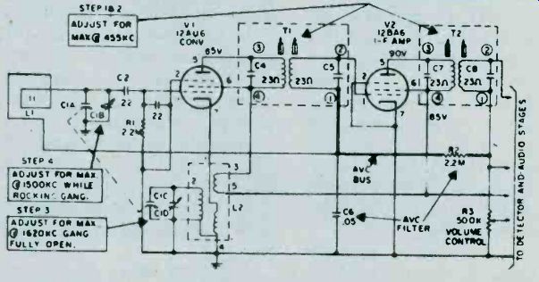
Fig. 3. Schematic of GE tube radio, showing AVC filter and bus. Since cathode
of V2 is grounded, tube relies on AVC voltage on control grid (pin 1) for
bias.
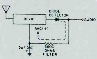
Fig. 4. As in tube sets, AVC in solid-state circuit is tapped from diode
detector.
The 0.1-second filter, therefore, is designed as a compromise which attempts to fit AVC response between the two extremes. In some advanced receivers, an AVC selector switch (Fig. 2) enables the operator to choose his rate to improve the receiver's performance on certain specialized signals such as code (CW), single sideband, or other non-standard carriers.
DC Up Front. To this point the circuit has developed a control voltage that's synchronized to incoming carrier strength. As shown in Fig. 1, the carrier has produced a shift of from-2 to-8 DC volts at the output of the fitter.
This is approximately the AVC voltage you'd measure in typical tube-type receivers. Now it's only necessary to provide a feedback loop to carry the AVC back to an earlier stage. How this is done is illustrated in the actual schematic of a typical tube radio in Fig. 3.
The AVC signal is developed across the diode load resistor and filtered in the resistor and capacitor indicated (R2 and C6). From there, the line is usually termed the AVC bus and extends back to the control grid of the IF amplifier. As an incoming signal grows stronger, a correspondingly higher negative AVC voltage is created. Result is that the gain of the IF stage is reduced accordingly.
Solid AVC. Millions of tube receivers still survive, but solid-state should end that era in a few years. Transistor receivers are subject to the same signal fluctuations and similarly require AVC circuitry. In looking at transistor circuits, you may find that the term voltage is often supplanted by current.
When discussing amplification in tubes, it's almost always a matter of controlling grid voltage, which is generally negative in polarity. (The current flow in a receiving tube grid is infinitesimal and usually ignored.) Transistors, though, may be discussed in terms of current since the terminal voltages (unlike tubes) are very low. Because of these differences, AVC action in tube circuits is usually described as negative grid voltage, while the solid-state version is in terms of base current.
Another difference is that the polarity of a receiving tube grid is almost always negative; transistor current, in contrast, may flow in either direction, depending on whether an npn or a pnp transistor is being controlled.
Schematics for solid-state AVCs are fairly close in appearance to tube versions, as shown in the typical portable in Figs. 4 and 5. Note that a sampling of carrier signal is taken at the output of a diode detector. At this point the carrier is already rectified to DC and needs only to be smoothed in the AVC filter. Note that the polarity of AVC voltage is shown as positive (+) since the transistors being controlled are of pnp type (Fig. 5). In pnp semiconductors, a positive-going voltage applied to the base causes lower current and a reduction in amplification (the reverse of a tube circuit). You will also find transistor AVC which runs in the negative direction.
This indicates an npn transistor is being controlled since its amplification decreases with the application of negative voltage.
Fig. 5 traces the major AVC points in a commercial solid-state circuit. Note that the carrier sample isn't trapped from the regular AM detector; instead, a separate AVC diode is connected to an earlier point in the receiver (see lower right of Fig. 5). This car receiver has an RF amplifier up front and it produces sufficient AVC voltage for the tap-off to occur at this early point. The remainder of the AVC bus resembles the tube circuit; the carrier is rectified, filtered, and applied back to the input stage. Since the RF transistor is a pnp type, an increasing carrier produces rising positive voltage and a consequent drop in transistor gain.
What's the Delay. AVC circuitry described to this point works well for table and other consumer type radios. But there's always something better.
One improvement is DAVC, for delayed AVC, to overcome one disadvantage of regular AVC on weak signals. To operate at highest sensitivity, a receiver should run wide open, or at maximum amplification. The trouble occurs when a weak signal entering the receiver commences to generate a small, but effective, AVC voltage. AVC comes on too soon and receiver sensitivity is prematurely reduced.
In the delayed AVC scheme, AVC must first overcome some fixed reference voltage before it starts to reduce amplification in the receiver's front end.
For example, a conventional receiver may start to generate AVC voltage when a carrier of about 5 microvolts is in the antenna. A high-performance ham or communications set, though, might delay AVC action until the signal attains a strength of 10 microvolts.
Another improvement in deluxe receivers is amplified AVC, meaning the control voltage is boosted before being applied back to an earlier stage. This could produce AVC voltage swings of from 0 to 35 volts, instead of a more conventional range of 0 to 7 volts. The net result is better control of the receiver under dynamic changes in signal strength.
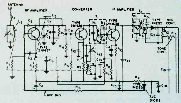
Fig. 5. Partial schematic of RCA car radio, showing separate AVC diode
(lower right) and AVC bus. Since transistors here are pnp's, AVC voltage
is positive rather than negative.
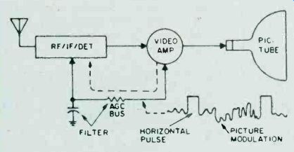
Fig. 6. In TV receiver, horizontal sync pulse must provide AGC voltage
since video carrier itself isn't suitable. Note that bask idea is same as
that used in AM and FM receivers.
It's AGC, Too. Though AVC began as a technique for controlling average audio level, nearly identical concepts are applied in receivers which produce pictures, navigational read-outs, or other intelligence of a non-audio nature. Since latter day AVC may no longer control volume, its designation changes to AGC, for Automatic Gain Control. Incidentally, this term is technically more accurate even for regular radios because it's receiver radio-frequency gain, not audio volume that's directly regulated. A good example of AGC is in TV receivers for keeping picture contrast reasonably constant over a wide swing of signal strength. Let's examine the TV signal in some detail because the method of generating a control signal is different from that of a radio.
The video carrier which brings the TV signal to the home is not a suitable source of AGC voltage. The picture carrier changes strength with lights and darks in the scene which happens to be on the screen during a particular moment. Back in our simple radio, we could filter out audio modulation fairly easily. However, video modulation can receivers are envisioned as having response equal to that of stereo FM tuners, on the order of 15 kHz. The introduction of AM stereo will finally force AM broadcasters to pay attention to the range of audio frequencies they transmit. Likewise, equipment manufacturers will devote more attention to the AM section of AM/FM receivers. Current design practice seems to regard the AM section almost as, a necessary evil.
DXers will find themselves hunting for distant stations broadcasting in stereo, and the improved AM receivers will be a boon for BCB DXers. Other special equipment, such as directional BCB loop antennas, will likely become available. Yet the improved audio range of AM stereo stations will cause more co-channel interference and may make digging out weak foreign stations on the "split" frequencies between the even 10 kHz frequencies a difficult task.
And. even those who only tune the shortwave bands may not be left out international shortwave broadcasts are AM, after all! Wouldn't you like to spend a cold winter evening listening to South Seas music from Radio Tahiti--in stereo?
=======