Recently I ordered a single-board computer that is used as a development system and trainer. It is a good microcomputer trainer and is used by many schools.
I was ready to begin finger-boning 6502 commands into the microcomputer when I noticed that the machine had no power supply. In my hast to get into this type of micro-computing, I had overlooked the power supply.
The company price list revealed a power supply, but it cost $50. Since it was only a 5-VDC, 4-amp, with ±12VDC, 500-mA on the side, it was easy to beat that $50 price.
There are several popular circuits used in power supplies for typical low to medium current range microcomputers. For really big computers, which require 25-ampere supplies, we will defer to the makers of commercial supplies.
The S-100 is probably the most popular mainframe microcomputer on hobbyist market. Also, there are plenty of industrial, scientific and engineering computers online and many of them are S-100 machines.
The S-100 system utilizes distributed voltage regulation. All digital devices, especially, TTL, require regulated DC power supplies. One approach is centralized regulation. In these machines, there is a 5-volt DC high current power supply located somewhere in the machine. It will supply the same power to all printed circuit cards plugged into the microcomputer-s motherboard.
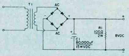
Figure 1. This circuit is designed for the simple s-100 power supply. The
transformer is a heavy duty Triad F-28U. It has dual secondary voltage ratings
of 6.3 and 7.5 volts AC at 25-amperes.
Lots of Current. It seems that a problem with a centralized system is that the voltage can be 5-volts only at one system location. Since these supplies draw large amounts of current there will be a sufficient voltage drop in the printed wiring tracks to reduce the voltage below the viable level for TTL devices (4.5 to 4.75 volts). Some power supplies, those that use feedback type regulators, have a sense line sampling the output voltage.
These power supplies are a little more useful because the sense line can be connected to the point on the motherboard where the voltage level is critical. The power supply will then attempt to keep the voltage at 5 volts DC at that point.
But at all other points, the voltage will be higher or lower, depending upon where the 5-volt line is connected to the PC board and how far that point is from the point of measurement. In my own Digital Group, Inc. Z-80 system, I measured the voltage at 5.25 at one point, and 4.8-volts at the far end of the system. If it had been any lower at to extreme end, some of the memory devices may have trouble functioning properly and if any higher it would have burned out TTL devices right and left.
Another problem with the centralized regulator system is the power supply cost. A 5-volt DC, 15-ampere power supply-cost. A 5-volt DC, 15-ampere power supply can cost a lot more than building an unregulated 8-volt S-100 power supply and then using buck apiece 1-ampere, 5-volt three-terminal regulators on each card.
Disaster. One final problem with the central method is the parts replacement cost if something should go wrong. If the series pass element of the power supply shorts or if the voltage reference element goes open, both events will cause the full unregulated power supply input voltage (8 volts on the S-100) onto the 5-volt bus-with disaster following for the TTL devices on the board.
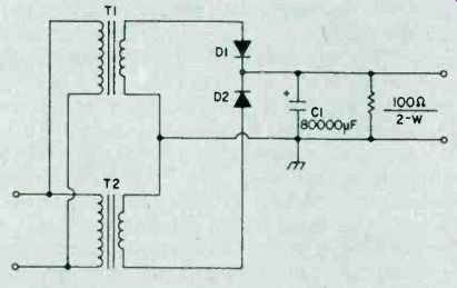
Figure 2. This is a viable but more expensive alternative, which is to
use two Triad F-22A transformers in a regular full-wave rectified situation.
This will deliver the 20-amperes which is needed.
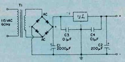
Figure 3. A substantial power supply circuit which forms the basis for
the more elaborate circuit which is presented in Fig. 4.
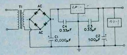
Figure 4. Probably the most commonly needed power supply for small, single-board
computers, this 5-volt DC, 5 ampere circuit is the smallest to be built
by the typical microcomputer hobbyist. The transformer is rated at 6.3-VAC
at 8-amperes.
When one of these big supplies opens up a shotgun blast of high voltage, there might be significant damage before the overvoltage protection circuit works. The higher the input voltage, with respect to the output (5VDC) line, the worse the damage. On the S-100 type of power supply, only the devices on the offending regulator are affected. While the other scheme could wipe out the entire system, the S-100 will burn up only the devices on the single board.
The problem is that we need to supply the 8-volts DC required by the array of three terminal 5-volt DC regulators used on S-100 boards. Furthermore, this voltage must be backed up with not less than 10 amperes of current for even moderate systems. For some systems, even more current is required.
Fig. 1 shows the circuit for the simple S-100 power supply. I have built this circuit into a Vector cabinet containing the Vector S-100 motherboard and there was plenty of 'room. Keep in mind when you use this cabinet, however, that the aluminum used in its construction will not support the transformer that I specify here. Place a piece of 1/4-inch plywood between the main support struts to support the transformer. Alternatively, cut up a 5- to 7-inch high piece of 19-inch rack panel to make the support.
The transformer specified here is the Triad F-28U. This heavy duty device is rated at 6.3/7/5 VAC, 25-amperes. The dual secondary voltage rating is one factor making this transformer more useful to microcomputer builders. The regulators used in S-100 require at least 8 volts DC at their input to operate.
Under fully loaded maximum current conditions, this level is sometimes hard to maintain using just a 6.3-VAC transformer, as we have only an 800-millivolt margin allowing for voltage drop. The 7.5 volts AC, however, will, when rectified, keep us in the gall game. The voltage is selected using the primary winding.
There are three lines to the primary: a common and two voltage taps. Select the primary tap that yields 7.5-VAC across the secondary.
Bridge Rectifier. Since this transformer is use in a bridge rectified situation, we cannot legally draw more than one-half of the 25 amperes it is rated to deliver. This 12.5 amperes will supply many small S-100 systems, but is insufficient for larger ones. We can stretch the point by properly of cooling the transformer. Overheating is due to exceeding the transformer's primary rating.
I have used this same transformer at 20-amperes in a bridge rectified situation and it ran . cool, because I placed a 100 c.f.m. muffin fan a few centimeters from the transformer. Place the fan so that it will blow along the same line as the laminations to maximize cooling. This will allow the air to blow into the windings, not into the fish paper covering on the outside of the winding.
The rectifier is any of the 25-ampere, 50 volt PIV (or more) stacs that are available. I used the General Electric GEBR-425 device. Be a little wary of some companies' ratings in this type of device; they tend to be optimistic to your detriment. I heat-slinked the rectifier using one of the larger finned aluminum sinks designed to TO-3 transistors (but undrilled to I could customize it for the rectifier). The rectifier/heatsink combination was positioned so that the air from the fan would also blow over the heatsink, improving heat transfer. Silicone heat transfer grease was used on the surface of the mounted rectifier.
The capacitor is probably the single most important part of this power supply. The nominal rating is given at 2000-uF to 50,00-uF range, depending upon whether or not you attempt to get the entire 25 amperes out of the transformer. But this is a minimum and in the case of the S-100 system, . I doubt the wisdom of the standard because of the distributed regulation system used.
I prefer to use as much capacitance as I can obtain. For my own power supply, I found an 80,000-uF at 15WVDC computer grade capacitor at a local distributer.
My recommendation is some value of capacitance between 75-000-uF and 200,000-uF even if two or more units have to be wired in parallel to achieve the value.
Small Load. The 100-ohm, resistor is used to place a small, minimum load on the power supply. It was found that output voltage was over +12 volts under no load conditions and that seemed a little too close to the working voltage of the filter capacitor. As a result, I tried various values of load, and found that 100-ohm, 2-watt seems the best solution.
When wiring this power supply, remember that when you are dealing with a high current situation. Use heavy duty wire and wire connectors in this supply. I recommend at least 8-gauge wire, or, two 12-gauge wires in parallel, for each run. Such wire sizes are not usually available in radio-TV parts distributers, but auto parts stores almost always carry them.
There are several alternatives to the transformer selected for this project. You could, find a surplus transformer rated at 6.3 or 7.5-VAC at bunches 0f current. These transformers are popular with the designers of high power radio transmitters as filament transformers and are occasionally seen in electronic surplus stores or in the hamfest markets. Or you could use the Triad F-22A transformers.
This is a 6.3-VAC, 20 ampere model, so is rated slightly lower than the F-28U that was specified. It will deliver 10 to 20 amperes in the bridge configuration, depending upon how brave you are. A viable, if expensive, alternative, is to use two Triad F-22.A transformers in a regular full-wave rectified situation (see Fig. 2). This will deliver the 20 amperes required. In this circuit, the primary windings are connected in parallel, while the secondaries are connected in series.
If you accidentally connect the secondaries backwards, then the output voltage will be zero. In that case, reverse the connections of either the primary or the secondary of one of the transformers. The problem is phasing the AC sine wave properly. Diodes D1 and D2 are stud-mounted 50 volt PIV, 25 ampere (or more) types. Again, the rectifier should be sturdily heatsinked.
Low Grade Supply. This power supply project is probably the lowest grade power supply that will be useful to micro-computerists. It is useful for small digital projects of any type using TTL (or CMOS operated at 5VDC) and some of the smaller single board computers.
The transformer can be any 6.3-VAC filament transformer rated at 2 amperes or more.
The rectifier is a bridge stack rated at 50 volts PIV, 1 ampere or more. The capacitor used in the filter fills the 2000-uF /ampere rule, although it would not hurt to used more capacitance. The output capacitor is strictly optional, although recommended because it improves the transient power supply response. It has a value that follows the rule 200-uF/ampere. It will be; happy with any value from 100 to 500-uF. The small value capacitors are used to improve the immunity of the regulator to noise on the input voltage line and from within the computer. These capacitors should be mounted as physically close to the regulator as possible. Most builders place them directly on the regulator terminals.
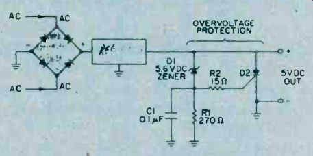
Figure 5. Circuit for adding overvoltage protection to your power supply.
The circuit is called an SCR crowbar, because it represents a brute force
method of doing the job of over-voltage protection.
The regulator itself can be any of the standard three-terminal 5 volt IC regulators: LM-309, 7805, LM-340-5, etc. Avoid the plastic TO-220 package types, as they should be limited to 750-mA unless well heatsinked.
Common Power Supply. The 5-volt, 5-ampere power supply (see Fig. 4) is probably the most commonly needed on small single-board computers.
The transformer for this power supply is rated at 6.3 VAC/8-amps.
There are also several regulators now on the market that will hack at 5 amperes. The regular that was selected was the Lambda Electronics, Inc. ( 515 Broad Hollow Rd., Melville, N.Y., 11746) type LAS-1905.
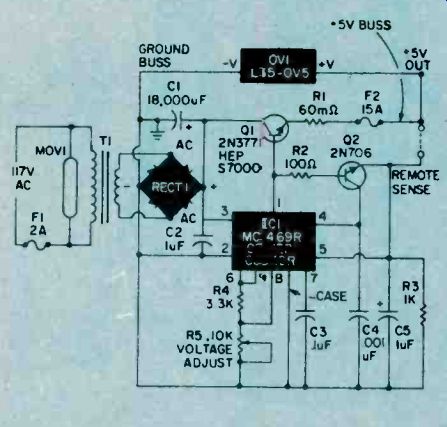
Figure 6. Circuit for a 5-volt DC, 10-ampere power supply.
The high current lines must be 12 gauge wire or larger.
The circuit features output current limiting to a constant 10-amps.
The rectifier used is the same 25 ampere rectifier; as used in the S-100 power supply project.
Follow The Rule. The filter capacitor (C1) follows the 2000-uF/ampere rule, so a 10,000-uF unit was selected.
Note that 8000-uF/25-WV-DC is commonly available.
The device labeled OV-1 in Fig. 4 is an over voltage protection module made by Lambda. These devices are designed to trip at 6.6-volts and will short the power supply line to ground if the voltage reaches this point.
If you wish to build your own overvoltage protection circuit then try something like the circuit in Fig. 5. The circuit is called an SCR crowbar, probably after the fact that it represents a brute force method of doing the job.
Diode D2 is a silicon controlled rectifier (SCR) and is rated to handle at least the current of the power supply. It is connected in parallel across the +5-volt DC output lines, but remains inert until a voltage appears at the gate terminal.
This triggering voltage is supplied by Zener diode D1.
At potentials less than 5.6-volts, the normal TTL operating range, the zener will not conduct current. But, at potentials greater than 5.6-volts DC the Zener conducts and creates a voltage drop across R1 that will fire the SCR. When the SCR turns on, the output lines of the power supply are shorted by ground. This will blow the primary fuse or burn out the transformer if there is no primary fuse.
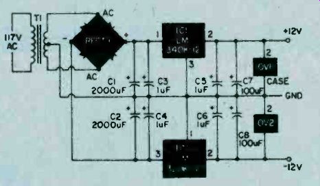
Figure 7. A plus/minus 12-volts DC power supply, this is a circuit that
is needed in the S-100 microcomputer, and most others as well. This power
supply is also useful for opamps, and other linear IC applications.
10 Amp Supply. Fig. 6 shows the circuit for a 5 volt rl0 ampere power supply. This is the circuit that I used on my first Digital Group, Inc. computer. The regulator is a Motorola MC1469R (HEP C6049R also works). There are two suffixes available for the MC1460; buy the one with the R otherwise, the rating is too low. This device is a 500-mA regulator but is insufficient to power the computer. We can boost the output current by using the IC regulator to control the base circuit of a series-pass transistor (2N3771). The heavy lines in Fig. 6 are the high current lines and there must be 12 gauge wire or larger.
This power supply features output current limiting, which means that the maximum output current, even into a short circuit, will be 10-amperes. The active element in the current limiter is transistor Q2. The base-emitter bias of this transistor is the voltage drop across the 60-milliohm (R1) resistor in series with the emitter of Ql. When the current reaches 10 amperes, the voltage drop is 0.8 volts, which is sufficient to turn on Q2 and shut down the supply. You can make a 60 milliohm resistor by connective five 0.33 ohm auto radio fusistors in parallel, or by winding one of fine gauge wire yourself.
The exact output voltage can be adjusted using potentiometer R5. Set the output voltage as close to 5.0 volts as you can.
The last power supply that we will consider here is the ±12 VDC, 1 ampere circuit shown in Fig. 7. This circuit is also needed in the S-100 microcomputer and most others as well. The transformer is a Triad F-56X (or equivalent), rated at 25.2 VAC at 2.8 amperes. The extra 800-mA gives us a margin of safety. Nowt: when buying the transformer for this supply, make absolutely sure that the transformer that you buy has a center-tapped secondary! The rectifier is a 2-amp or greater bridge stack rated at 100 WVDC or more. Note that we are not using the rectifier as a fullwave bridge, but as a pair of half wave bridges, with the transformer center tap as the zero-volt reference. The output of one half-bridge will be negative to ground, while the other is positive to ground.
The filter capacitors are selected for the 200uF/ampere rule, but should be higher because this circuit uses halfwave rectifiers. I recommend that you use 2000-uF for light-duty loads, but 3000-uF or 5000-uF or more for the full 1-ampere per side. This will compensate for the halfwave voltage rectification.
This power supply is also useful for operational amplifiers, and other linear IC applications.
=======
Also see: Inside Your Power Supply