The catalog of a leading electronics supplier contained this glowing description: A superhet shortwave receiver covering the standard broadcast band through 20 Meters. Its cabinet was luxurious walnut, its audio output push-pull into a high-quality speaker. The set boasted low current drain and the latest circuitry. The price?--a mere $49.75.
The catalog was Allied Radio's and the date was 1932. The radio was a console meant for the living room, and it no doubt pulled in the A&P Gypsies with reasonable fidelity. The thing is, it required batteries for power.
Here's the battery complement for the handsome, but hungry. Knight 8 vintage receiver: three 45-volt "B" batteries for tube plates; one 2-volt "A" cell for lighting filaments; one 22.5-volt "C" battery for biasing tube grids. This mountain of Eveready’s cost $9.00, a rather steep tab even in the good old days. And they could have pooped out right in the middle of a Herbert Hoover speech.
Super Supplies. That danger is gone, thanks to power supplies. Now a receiver takes raw electricity from the utility company and converts it to filament, plate, or bias voltages. It does the same for transistorized circuits. Or it perhaps participates in the growing trend to 3-way operation, where you use the same device at home, in a car, or carry it as a portable. The supply not only powers the equipment in the home, it also recharges the portable batteries.
Cost is low because AC power is priced about 7' per kilowatt hour--which means you can operate a plugged-in table radio for about 100 hours on a few pennies per day.
Though power supplies operate circuits of vastly different voltage and current requirements. the basic principles are the same. In most instances a supply accepts house current-usually 117 volts AC alternating at 60 Hz (cycles)-and performs the following steps.
Transforming Voltage. The power company provides 117 volts for home outlets, but it's hardly the value that many electronic devices demand. The plates of receiving tubes require about 100 to 250 volts for operation. while transmitting tubes may need a "B+" several hundred volts higher. Transistors, on the other hand, usually function at less than 30 volts. So the first task of the supply is to transform voltage to the desired value. In many CB sets, for example, there's plate-voltage requirement of 250 and filament-voltage requirement of 12.6 VAC. The power transformer delivers these levels.
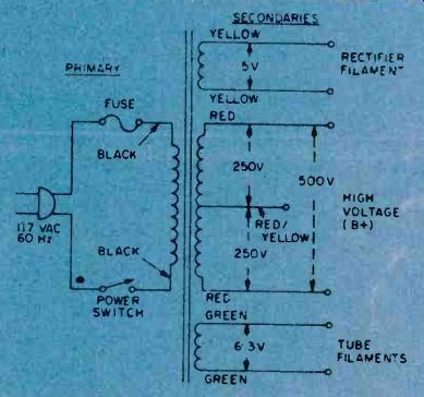
Fig. 1. Schematic of typical power transformer, showing voltages and EIA
color-coding of transformer windings.
Changing AC to DC. Furnishing correct voltage is not enough. Those voltages must often be DC-and the power company provides alternating current. So the second function of a supply is to rectify, or convert AC to DC. If a rectifier malfunctions in your radio you'll soon learn its function. The symptom is annoying hum in the speaker (caused by 60-Hz alternations in the audio). In a TV set, suffering rectifiers can put a thick, dark, "hum" bar across the screen.
Filtering. Though rectifiers change AC to DC the product is far from suitable because it contains objectionable ripple. This will be attacked by the filter, which smooths the pulsations to pure DC. The final step of the supply depends on the designer. He can add a bleeder, choose a regulator, or insert a divider at the output. We'll look at these extras, but first consider how the supply's basic parts operate.
The Transformer. In Fig. 1 is a typical power transformer that's been produced by the millions with only slight variations. As we'll see, the transformer acts to create a voltage change between its primary and various secondary windings. The trick's based on the turns-ratio between the various windings. If turns in the secondary number twice those of the primary, then output voltage doubles: if turns in the secondary are a fraction of those in the primary, then a stepdown in voltage occurs.
Thus, in Fig. 1, the rectifier filament, which operates at 5 volts, has few turns compared to the primary; the high-voltage winding at 500 volts, however, has about five times as many turns as the primary. The colors shown for the windings, incidentally, are standard and observed by many transformer manufacturers.
The center-tap connection of a winding splits the voltage in half. In our example, the' high-voltage secondary is capable of 500 volts across the full winding (red to red), but only 250 volts between the center-tap (red/yellow) and either end. The most important job for a center-tap occurs in a full-wave supply, as we'll see in a moment. Note that a protective fuse and a power switch are located in one primary lead of the transformer.
Rectification. The two filament voltages from our transformer (5.0 for the rectifier and 6.3 for other tubes) will heed no further processing. AC can be applied directly for filament heating (or for lighting pilot lamps on the front panel) . High voltage, however, must be converted to DC before powering tube plates or transistor collectors and drains.
A circuit for changing AC and DC is a half-wave rectifier, shown in Fig. 2.
It's based on a diode's ability to conduct current in only one direction. The rectifier cathode boils off electrons (negative) which are attracted to the plate when the plate is driven positive by incoming AC. When the next half-cycle of the AC appears, the plate is driven negative, so electrons are repelled at this time. The net result is shown in the output: a series of positive voltage pulses appearing at the load. (The dotted line shows where the negative side occurred.) In practical circuits the half-wave rectifier is usually reserved for light-duty power supplies. It's inefficient because it fails to make use of AC-voltage half the time (during the negative pulses). Secondly, those wide spaces between pulses are difficult to filter because of low ripple frequency. In a half-wave rectifier, the pulsations occur at 60 Hz, the same frequency as the applied line voltage. But don't underrate the half-wave supply because it's been used in just about every 4- or 5-tube table radio now playing. After all, its power requirements are low and the circuit is inexpensive to manufacture.
Full-Wave Supplies. Transmitters and higher-power equipment overcome the half-wave's shortcomings with the full-wave system. It's nothing more than a pair of diodes that are driven alternately so they consume every bit of AC input voltage. The key to full-wave operation is the center tap on the transformer's secondary winding. As applied AC appears across the complete winding, jt makes the top end negative (as shown in Fig. 3) and the bottom end positive.
The center-tap at this time establishes the zero voltage point because it's at the common, or grounded, side of the circuit. During the time the lower diode (No. 2) has a positive plate, it does the conducting. Next, the applied AC voltage reverses and makes the top diode plate (No. 1) positive so this tube now conducts.
This load-sharing combination of two diodes and a center-tapped power transformer not only improves efficiency, but doubles the ripple frequency. An input of 60 Hz emerges as 120 Hz in a full-wave arrangement because every half-cycle appears in the output. This reduces the pulsating effect (cycles are closer together) and the DC becomes easier to filter.
If you purchase a transformer, watch out for one pitfall. It may be rated, say, "250 volts CT" and appear to be suitable for a rig with a 250-volt plate supply. In a full-wave supply, however, the transformer voltage output would be only 125, since a center tap reduces the voltage of a winding by one half. This can be avoided by specifying a transformer that has 250 volts each side of centertap or, stated another way, "500 volts CT."
Solid-State Rectifiers. Tube rectifiers are still widely found in electronic equipment. but they're destined for the Smithsonian Institution. Solid-state equivalents are superior because they don't need filaments or heaters to accomplish the, same rectifying action.
They're several hundred times smaller and much cooler in operation. Instead of a huge 5U4 vacuum-tube rectifier in your TV set you're now more apt to find a pair of tiny silicon diodes.
Circuits using these semiconductors, though, are similar to those of vacuum tubes. As shown in Fig. 4, diodes can be used in equivalent half- and full-wave arrangements.
Unlike tubes, though, solid-state diodes rectify AC and DC by a semiconductor effect at the diode junction (a region between the anode and cathode). The action, in simplified fashion, occurs when "current carriers" in the material flow toward and away from the junction under the influence of applied AC. When few carriers appear at the junction, little, current gets through the diode; conversely, when many carriers are in the area, they reduce the junction's opposition to current flow.
Depending on the way the diode is connected in the circuit, it can recover either the positive or negative half of the AC. Bridge Rectifiers. Another common arrangement is the full-wave bridge (Fig. 5 ) . Though it uses four diodes, it offsets this disadvantage by an ability to produce the same output as a regular full-wave supply without a center tapped transformer. It accomplishes the feat by operating one pair of diodes during each half cycle. And as one diode pulls current out of the load, its partner pushes current into it.
The net effect is a total voltage across the load which is about equal to the applied AC. We've shown how it (recurs for diodes 1 and 2 in the diagram (Fig. 5) but a comparable action occurs in the other diodes when the A switches polarity.
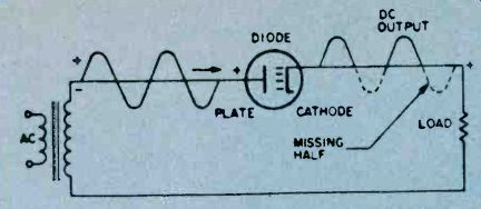
Fig. 2. Half-wave rectifier, showing how diode produces pulsating DC output
by repelling electrons when plate is driven negative.
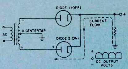
Fig. 3. Full-wave rectifier is a pair of diodes driven alternatively to
take advantage of both halves of AC input voltage.
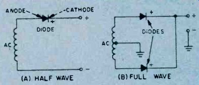
Fig. 4. Solid-state selenium or germanium diodes in similar half- and full-wave
rectifier circuits are better than tubes since they don't need filaments
or heaters for rectifying action.
Filtering. The next major section of the supply is the filter, which smooths out the ripple. Its two major components are often a capacitor and a choke which eliminate pulsations by dumping a small amount of current from the peak of each ripple into the "valleys" between them. The result, as shown in Fig. 6. is pure DC fit for a tube or transistor.
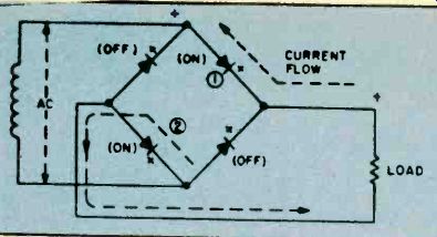
Fig. 5. Solid-state bridge rectifier provides full-wave rectification with
center-tapped transformer by using four diodes.
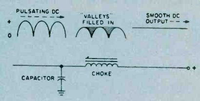
Fig. 6. Curves depicts how reactance of choke and discharge of capacitor
eliminates ripple and fills in valleys for smooth DC.
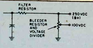
Fig. 7. Choke can be replaced by filter resistor. Also shown is bleeder
resistor that serves both as output regulator as well as voltage divider.
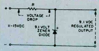
Fig. 8. For more efficient regulation than produced by bleeder resistor,
zener diode shunted across DC output will hold voltage to specified limit.
In operation, pulsating DC arrives at the filter choke. a coil of wire wound on a soft iron core. As the name implies, the choke attempts to oppose any change in current flow. The rippling part of the wave, therefore, encounters high reactance in the choke and fails to get through. This is aided by the filter capacitor which is charged by ripple voltage.
As the ripple falls (between pulses). the capacitor discharges part of its stored current into the "valley." Thus the combined effect of choke and capacitor results in smooth DC which can have ripple as low as a few percent of the total voltage.
You won't find the choke in some power supplies because it's an expensive item. Many designers eliminate it (especially in mass-produced equipment) by using a resistor instead, as shown in Fig. 7. The resistor does the job of filtering, but with one penalty: it reduces the amount of available voltage at the output. Yet, the loss can be tolerated in many circuits and filter resistors are common.
Another use for resistors in a supply is to serve as a bleeder. also shown in Fig. 7. In this function, it protects parts in the supply from possible damage due to sudden voltage surges when the supply is first turned on. Also, a bleeder helps stabilize voltage output when the load changes (as in a keyed ham transmitter) by always drawing some small degree of load current. Bleeders, too, are found in dangerous high-voltage circuits where they bleed-off the stored charge of filter capacitors that could deliver a lethal shock to a repairman (even after the equipment has been turned off.) Note that a tap can be added to the bleeder to provide a second output voltage from the supply. Now the bleeder becomes a voltage divider. As such, it can supply the designer with multiple output voltages for operating various devices in a circuit.
Voltage Regulation. A ham who's received a "pink ticket" from the FCC for chirpy signals, a color TV that's gone fuzzy, a shortwave receiver that won't station frequency-all may suffer from a problem in voltage regulation.
Line-voltage fluctuations or other electrical swings can cause poor, unstable operation. So the engineers have come up with methods for "stiffening" a power supply.
If, say, line voltage changes from 105 to 130, they design the circuit to operate at 100 volts. Whatever voltage arrives over the line is reduced to 100, and the surplus is dumped (usually in the form of heat). To perform this task, the regulator establishes a reference point, then regulates around it.
A common example is the zener diode found in the power supply of many CB transceivers. Since these rigs can operate from a car's battery or generator, supply voltage can swing from 11 to 15 volts. This could happen if you're standing for a traffic light, then pull away, causing a shift between car battery and generator. If the CB set is on at this time, receiver tuning could be thrown off because of large changes in local oscillator voltage.
A zener diode can compensate for the shift, as shown in Fig. 8. At first glance it appears as an ordinary diode connected backward. Since the cathode (upper) terminal is connected to the positive side of the supply, there's a "reverse bias" condition. A zener diode, however, "breaks down" (or "avalanches") whenever its rated (zener) voltage is exceeded. In our example, the zener is a 9.1-volt unit, so the diode conducts current as the supply voltage shifts from 11 to 15 VDC. Yet we see 9.1 volts indicated at the output. Secret of the zener's ability to hold at 9.1 is that it detours part of the supply current as the voltage increases.
Since a resistor is in series with that current flow, a voltage drop (as shown) appears across the resistor. Thus, any increase in supply voltage is dissipated across the resistor and effectively subtracted from the output. This automatic and continuous action occurs for any voltage above 9.1-the zener's nominal rating-so the output is said to be regulated.
Fusing Power Supplies. You can protect your power supply by installing a fuse or circuit breaker on the primary or secondary side of the transformer. A fused primary gives good overall protection but does not have the sensitivity needed for some circuits.
By installing a fuse between the transformer's secondary center tap and ground you can improve fusing sensitivity. In solid state circuits the value of the fuse is all-important due to the low voltages involved, but since fuses do not react fast enough to save a transistor or IC chip you might have to resort to semiconductor protection such as using a zener diode.
More and Merrier. This barely brushes the subject of power supplies, since the variations are nearly endless.
More than 20,000 volts for the picture tube of a color TV are derived from a special "flyback" transformer. It captures voltage from rapidly moving magnetic fields in the set's horizontal scanning section. An oscilloscope power supply contains strings of adjustable voltage dividers to move the pattern of light on the screen in any direction.
There are also high-current supplies with massive rectifiers for battery charging and super-smooth lab supplies for circuit design. But behind most of them are the simple principles which transform, rectify, filter, and regulate a voltage so it can do the job at hand.
=======
Also see: Power Supplies for IC Circuits