In this section, ELECTRONICS THEORY HANDBOOK will describe the origins, theory and uses of two important pieces of test equipment, the Frequency Counter and the Digital Multimeter (DMM). Both have distinct advantages over their analog counterparts and are now used widely by technicians and hobbyists in virtually every area of electronics.
The Digital Multimeter
THIS HANDBOOK, ATTEMPTS to introduce its readers to new developments in instrumentation, will now discuss advances in the measurement of voltage, current, and resistance. In the past, measurement of these parameters have utilized analog devices; however, with the advent of large scale integration semiconductor chips, a new generation of digital sampling techniques has been developed that allows accuracy to laboratory standards with moderately priced equipment. Full appreciation of the flexibility and advantages of the newer digital devices is apparent when comparison is made with analog equipment.
The relationship between current and voltage for steady state linear direct current applications is called Ohm's Law. This "Law," the most basic concept of electronics, is written
E = IR
The basic unit of voltage (E) or electromotive force is the volt. The basic unit of current (I) or time rate of change of charge is the ampere. Resistance (R) is measured in ohms.
IMPEDANCE
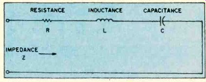
Things become more complex when steady state AC circuits are investigated. The units of voltage and current do not change; however, there is now a dynamic relationship between voltage and current which must take into consideration the phase angle between these two parameters. Simple DC resistance becomes a complex impedance. Impedance by definition is voltage divided by current and is the sum of the resistive plus reactive components of the circuit. Coils and capacitors determine the magnitude of the reactance of a given circuit. It is beyond the scope of this article to deal in depth with the problem of complex impedance, but some knowledge is necessary for an understanding of voltage measurements.
The DC resistance of an ideal capacitor is infinity.
Actual capacitors have leakage dependent upon their composition, e.g. electrolytics will have much more leakage than ceramic or mica capacitors. An ideal inductor has zero resistance. Actual inductors have a series resistance which is a function of diameter, temperature, length, and composition of the wire used in their windings.
Under transient and AC conditions, the current flow in an inductor always lags the voltage flow, whereas the current in a capacitor always leads the voltage.
Any measurement of voltage under these conditions must take into consideration the changing nature of voltage and current flows and the impedance of the measuring device.
--------COMPONENTS AFFECTING IMPEDANCE
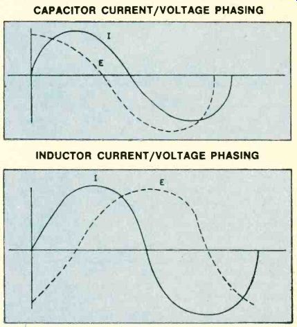
--------CAPACITOR CURRENT/VOLTAGE PHASING
---------INDUCTOR CURRENT/VOLTAGE PHASING
DESIGN CRITERIA
Certain criteria can be formulated concerning the equipment used to measure direct or alternating currents or voltages. First, the device should be accurate and capable of measuring both AC and DC currents or voltages. Second, linearity should be present over a wide range of readings. Third, the impedance of the device should be sufficiently high so as not to "load down" the circuit being measured. Fourth, measurements of resistance should be taken at low voltages so as not to alter the resistance of complex circuits that consist of active and passive elements. Last, the readings should be reproducible and not a function of the temperature, humidity, or the supply voltages necessary to power the measuring device.
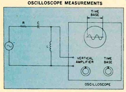
---- OSCILLOSCOPE MEASUREMENTS
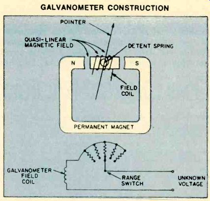
---- GALVANOMETER CONSTRUCTION
THE STONE AGE
In the past, several methods were used to accomplish these. goals. For AC, high frequency, and transient measurements, the oscilloscope provided the "gold standard" for a reproducible, high quality, high impedance device that had reasonable linearity. If the device was well calibrated, and had gain stability, measurements to two significant figures could be made over a wide range of voltages and frequencies. By use of suitable coupling devices, measurements of current could also be made. With appropriate attenuators. an oscilloscope could be made to have an input impedance of 10-megohms which was sufficient for most circuits. The phase relationship between voltage and current was easily demonstrated using dual sweep or chopped-beam oscilloscopes. Difficulties were commonly encountered with DC and very high frequency AC measurements. and with obtaining an accurate time base for the horizontal sweep circuit. Finally, the oscilloscope was not portable and proved to be a fragile device that was tied to a service bench.
Most measurements of voltage. current, and resistance not done on an oscilloscope were obtained with portable devices using D'Arsonval galvanometers called "meters." These devices, like the oscilloscope.
suffered from several major faults. First, because of distortion in the magnetic field. true linearity was never achieved over the entire range of readings. Second, accuracies of only two or perhaps three significant places were available. Third, as with the oscilloscope, under certain conditions parallax (difference in reading that is dependent on the position of the observer)
was a major problem. Fourth, the basic resistance of the galvanometer was low, on the order of 20,00040,000-ohms-per-volt for expensive equipment, and 5,000-10,000-ohms-per-volt for less costly gear. Impedances, when AC voltages were measured, were commensurately lower-on the order of 1,000-5,000 ohms. Lastly, the devices were basically fragile and easy to burn out. In spite of these shortcomings, the analog volt-ohmmeter was and is a popular, inexpensive device that sells for prices ranging from approximately $10 to $150, depending upon the accuracy, ranges, functions, and input resistance.
True laboratory standard accuracy-voltage readings to three and four significant places-could be obtained using D'Arsonval-type devices that operated over very narrow ranges and were used in bridge circuits that compared the unknown voltage to a known standard voltage. Unfortunately, this equipment was expensive, difficult to use, and not portable.
In another class of devices, the low basic input resistance of the galvanometer was improved by using vacuum tubes (VTVM) or semiconductor devices (eg, FET). Unfortunately, this was done at the expense of doubling the price of the equipment and adding the problem of gain stability and input offset voltages.
DIGITAL DESIGNS
With the advent of large scale integrated circuits, an alternate means of measuring voltage, current, and resistance became available. This class of devices converted the analog signal, e.g. the current, voltage, or resistance, and displayed it in digital form. Higher accuracies were obtained by expanding the scale of measurement and eliminating meter reading errors--parallax and nonlinearity. Therefore an order of magnitude advantage was obtained. For example, if a high quality volt-ohmmeter had an accuracy to 1 percent of a given reading, similar quality digital devices could be made to read to 0.1 percent accuracy. Such an advantage is obvious when analyzing complex circuitry using semiconductor components. Furthermore, the ohmmeter function of these new generation digital devices uses very low currents when compared to the standard volt-ohmmeter. Lastly, the input impedance of these devices is in the 10-megohm range, shunted by a small capacitor of approximately 50 pF.
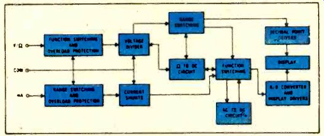
------- TYPICAL FUNCTION DIAGRAM
Digital volt-ohmmeters are only as good as their amplifier stability and linearity, internal voltage and time references, and method of eliminating offset voltages. Various schemes have been devised to provide automatic zeroing, programmable or long term stability, and minimal offset voltages. Input signals are converted into a scaled DC voltage, which is then transformed into a digital readout by integration, logic, and display circuits. DC voltages to be measured are applied across a voltage divider. A decade fraction of this voltage is selected by the range switch. The signal
is then passed into a DC voltmeter which consists of an automatic offset correction (auto zero) circuit, a dual slope integrator, and a digital processing and multiplexing device. The reference voltage is derived from a highly stable Zener diode.
---------Heath's 1M-2212 digital multimeter offers auto-ranging, which
selects the proper voltage, current, or resistance range for more convenient
measurements. It weighs 8 lbs., less optional NiCads.
AC MEASUREMENTS
AC voltages are measured in a similar manner, […] the unknown current through a precision shunt-resistor which develops an AC or DC voltage proportional to the current in the shunt resistor. This voltage is again applied through the bridge (for AC currents), buffer, and integrator circuits. Various degrees of auto ranging are available depending upon the design and price of the instrument. This auto ranging refinement allows wide ranges of voltage to be measured with one setting of the range selector without internal overload.
Some manufacturers offer a high low ohm feature that permits in-circuit resistance measurements at voltage levels below the conduction threshold of semiconductor. The high ohm feature allows semiconductor junction tests by measurements of forward and reverse resistance ratios.
ACCURACY
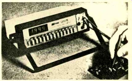
------------B&K Precision's model 2830 digital multimeter offers 4-place
red LED readout, high/low resistance range selection, direct DC/AC current
readout, a convertible carrying handle and desk prop.
As mentioned earlier, the specifications of digital multimeters are normally in the range of 0.5 percent of the reading, plus 0.1 percent of the range r one count for DC voltages. A display reading of 1.00-volt DC from a low impedance source will have an uncertainty of ± 0.0035 volts; a truly amazing feat. Because of the sampling nature of the device and the auto ranging features, response time is usually less than 3 seconds to within stated accuracy. Settling time for the semi-ranging devices (100 percent overvoltage) is typically 1 2 of a second.
Optimal performance can be obtained by observing a number of precautions when test measurements are made. Ground loops must be avoided since differences of ground potentials may set up loop currents and distort the measured value. Problems of this type can be almost completely eliminated by using battery operated equipment. Ground loops may be lessened by connecting the test source ground to true earth ground if possible. In floating DC or AC measurements, it is possible to introduce a common mode voltage by reactive coupling when the line cord is connected.
Again, problems of this type can be almost entirely eliminated by using a battery operated meter. If only AC operation is available, this type of measurement should be made on the highest range possible consistent with usable measurement resolution. Most devices will handle up to a 100 percent full range over-voltage with meaningful readings.
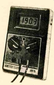
----------- An example of a handheld digital multimeter is IRK Precision's
model 2815. The new 1.51 IC has built-in shielding against strong RF
fields, making it a hot item with hams, CBers and radio techs.
The basic design features of the digital multimeter make it the ideal replacement for the existing analog multimeters and FET VOMs or VTVMs. In addition to providing equivalent functions and range, the inherent accuracy and features of this type of instrument provide a significant margin of improved performance over comparably priced analog meters. Digital multi-meters are priced from $60 to several hundred dollars and come in kit or assembled form. Outstanding examples of this type of instrument are the Heath model IM 2212 auto ranging digital multimeter kit, the B&K Precision 2830 31/2 digit multimeter, and the new inexpensive Radio Shack model 22-197 hand-held liquid quartz 31 digit display unit.
CONCLUSION
In summation, the proven stability of dual-slope integration combined with precision, ratio-trimmed resistor networks and advanced LSI technology has generated a series of digital multimeters that provide extreme versatility and accuracy at an affordable price.
They have virtually made the hand-held galvanometer-based analog volt-ohmmeter obsolete. Their major drawback is in their time to settle on a given reading and the necessity of using sampling techniques. They are an exciting, accurate, and dependable way of making basic measurements of voltage, current, and resistance in modern electronic circuitry.
The Frequency Counter
THIRTY YEARS AGO FREQUENCY counters were large expensive devices reserved for colleges, the military service, and those repair facilities that had the funds to afford a counter. Most frequency measurements were done rather crudely with oscilloscopes using either Lissajous patterns or a calibrated time base sweep circuit. In any event exact frequency measurements were rarely available to the average experimenter. With the technological explosion promoted by the ever expanding consumer electronics market the need to accurately determine frequency has become apparent.
Digital display of frequency or time which was once a rarity has now become commonplace.
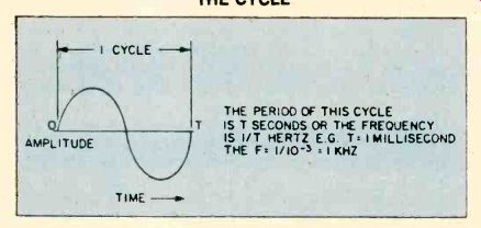
-----------THE CYCLE
=========
GLOSSARY OF TERMS
BCD CMOS DTL FET FF LED LSI RTL SSI TTL
Binary Coded Decimal Complementary Metal Oxide Semiconductor Diode Transistor Logic Field Effect Transistor Flip Flop or Bistable Multivibrators Light Emitting Diodes Large Scale Integration Resistor-Transistor Logic Small Scale Integration Transistor-Transistor Logic
==========
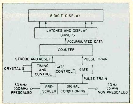
-------------- COUNTER BUILDING BLOCKS
HOW THEY WORK
The unit of frequency measurement is the Hertz. Frequency also implies time since the Hertz by definition is a cycle per second. Therefore, the period of a given frequency is defined as the reciprocal of that frequency.
This can best be visualized by examining this diagram.
The simplest serial counter is one made up of two bistable devices known as "flip flops". This two bit serial counter has four distinct states. It is important to note that this device counts in the binary number system. Adding an additional flip flop will yield 2', or eight states, and adding N flip flops serially will yield 2N states. Unfortunately our number system uses the base ten, not the base two. For example. the number ten in our decimal system would be 1010 in the binary or base two system. Any base ten number has an equivalent "binary coded decimal" (BCD) number.
If a precise gate interval is used in conjunction with the counter just described, frequency could be determined from the number of cycles counted during the gate period. A gate period of one second would yield a frequency equal to the number of cycles counted during this gate period. Likewise, if the gate period was .1 second, then the frequency would be 10 times the number of counts. After counting the number of pulses or counts in a gate period, some method must be devised to display and store this information until the frequency is updated during the next counting period. The scheme then consists of a clock oscillator which generates the gate period, a decade counter, and latch and digit driver elements plus the actual digital display.
ACCURACY
The frequency counter's accuracy is a function of its time base stability (accuracy of the gate period), which is dependent on the quality of the quartz crystal. Most counters use either the readily-available color burst TV crystals (3.579545 megahertz) or other specially designed crystals in the 4 to 10 megahertz range. To achieve a 1 part per million accuracy in the count frequency requires that the crystal oscillator have no more than 1 part per million drift over the temperature range 20 to 40 degrees centigrade (ambient temperature). Stability is achieved by pre-aging this crystal.
In the past, discrete digital elements were required in the design of a frequency counter. These sub-units were formed of "small scale integration" (SSI) building blocks of individual "diode transistor' logic" (DTL) or "transistor-transistor logic" (TTL) circuits. With the advent of "large scale integration" (LSI) circuitry, it is possible not only to include a decade counter and gate within a single chip but also to place the latch circuitry and "light emitting diode" (LED) segment drivers all in one module. A typical example of such an LSI chip is the 7208 manufactured by the Intersil Corp. The maximum signal frequency which a typical LSI decade counter chip can handle is between 6 and 7 megahertz. This device is not designed to handle sinusoidal inputs as are commonly encountered during servicing applications. Also, frequencies up to 600 megahertz are now in common use.
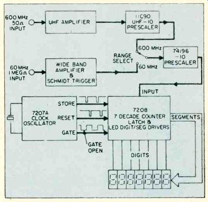
------------PRESCALER AMPLIFIERS
VERY HIGH FREQUENCIES
The usefulness of a given counter chip can be extended by pre-scalers. A prescaler is a BCD device which counts an input frequency and divides it or pre-scales it to a desired output frequency. For example, if a 60 megahertz signal is to be counted by a device whose maximum frequency is in the 6 megahertz range, then a divide-by-ten circuit is necessary for useful counts to appear. Pre-scalers usually are SSI devices which consist of a number of flip flops that divide the incoming frequency, "square it," and present a pulse for every tenth cycle of the original frequency. Extension of the frequency range to the 600 megahertz region can be obtained by coupling additional pre-scalers that are specifically designed to work at these frequencies. Useful input impedances and high sensitivities are obtained by placing amplifiers in front of the prescaler.
The input impedance of the wide-band mid-frequency amplifier is typically 1 megohm and obtained by bipolar "field effect transistors" (FET's). Amplification is then achieved by a broad band multi-stage receiver that commonly has a Schmidt trigger to "square up" the output.
The advantage of high input impedance in this frequency range is quite evident, since most harmonic oscillators will cease to operate or shift frequencies when loaded by a few thousand ohms. UHF prescalers have reasonable sensitivity without pre-amplification but again some means of impedance matching must be obtained. This is commonly done with a high frequency RF transistor and special UHF techniques to keep self inductance at a minimum and prevent possible attenuation. High input impedance in the UHF/VHF range is not desirable since the reactance of shunt capacitance is present in coaxial input cables, jacks, and various leads.
Therefore, a nominal input impedance of 50 ohms is used for counting in the UHF/VHF range.
------------The MAX 100 from Global Specialties Corp. is a portable eight
digit counter for field or lab use. Range is 20 Hz lo 100 MHz.
----------The Optoelectronics Model 7000 is a very compact Frequency
Counter kit with seven digits and a resolution of 10 Hertz up to 60
Megahertz. It covers up to 550 Megahertz. This photo shows the upper side
of PC board, including the battery pack. A good amount of wiring mounts
on the other side of the board too.
CHOOSING A COUNTER
Frequency counters are available both in kit and assembled forms and, depending on the price range, various options are available including initial zero suppression, gate indicators, AC and portable DC operation, attenuators, and temperature compensation of the crystal oscillator.
Any counter will perform properly when connected to the output of a pure sine wave signal generator. In many instances, however, frequency measurements must be made on complex electrical signals. In general, a signal may have an irregular wave shape containing noise and harmonics. It may also be combined with higher and/or lower frequency signals of reduced amplitude. When noise spikes and interference are present. the count may appear unstable and a significant amount of error can result. Noise or interference therefore can be seen by the counter as a signal and an erroneous reading may occur.
THE WRONG NUMBERS
Some inexpensive frequency counters have a remarkable tendency to display totally inaccurate counts that are both stable and reproducible. This condition can occur when the input signal level is just below the counter's sensitivity threshold. The counter's input amplifier tries to amplify and convert this low level signal into a countable square wave. Unfortunately there may be no indication when this condition occurs because the frequency displayed can be higher, lower, or fairly close to the actual frequency. Some high priced counters have a feature called clean drop-out, where all zeroes are displayed whenever the input signal is less than the counter's sensitivity threshold. Special precautions must therefore be taken when using inexpensive counters and measuring complex signals that are at or just above the threshold sensitivity. Accurate measurements can only be made with some knowledge of the counter's characteristics.
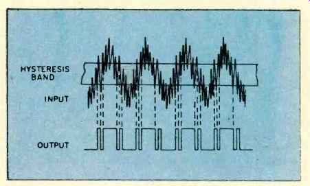
Most counters use Schmidt triggering circuits to "square up" input signals before counting takes place.
Such a trigger has a hysteresis band between triggering points. Counter circuits usually trigger on the trailing edge of a square pulse.
---------------DERIVING SQUARE WAVES
Commonly used methods to prevent these problems consist of attenuation of the signal with significant noise, removal of dc components, increasing the signal So the counter when there is significant harmonic distortion, and eliminating ringing by the proper selection of a series damping resistor. Analyzing a few of these methods may prove useful in developing a practical approach to the problem of frequency measurement.
COUPLING
Let us assume that we have a signal that has ringing. This ringing will cause false triggering at every crossing of the hysteresis band as shown.
A series damping resistor which acts as a low pass filter will effectively diminish the amplitude of the riving while leaving the basic frequency of the fundamental component unchanged.
The effect of such a series damping resistor can be analyzed as follows: for frequencies less than 60 megahertz, most counters have an input impedance of approximately one megohm and require a 10 millivolt signal for a consistent count.
The easiest method of coupling an unknown signal to the counter is by means of a short length coaxial cable. A 2 1/2-foot length of coaxial cable has a shunting capacity of approximately 80 picofarads. The input capacitance of most counters is approximately 20 pico-farads. Since these two capacitances are in parallel, the total capacitance seen by an external load is approximately 100 picofarads. A simple resistance in series with the coaxial cable will form a voltage divider. The voltage across the shunt capacitance would be equal to:
V = V / (R WC+1) where W=2v-f counter signal Damping
Maintaining a voltage of approximately 10 millivolts across the input of the counter will then require a damping resistance of the order of:
R = V / WCXIO' if V »1O-' Volts Damping signal--signal
A good compromise is to place a ten thousand ohm resistor in series with the coaxial cable for adequate damping of most signals.
When signals in the audio range are analyzed, a more elegant low pass filter should be placed in series with the probe. A two-stage filter with a 12 dB per octave final band pass attenuation is seen in the next figure.
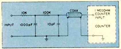
------- LOW PASS PROBE
Here, the two cut-off frequencies are arbitrarily chosen at 10 kilohertz and 100 kilohertz and may be changed by varying the resistor-capacitor combinations of (R,, C,) and (R2, C2). RF measurements in the high frequency to ultra high frequency range can be accomplished either through use of small whips, "rubber duck" antennas, or more elaborate coupling techniques. Feed-through terminators such as the Heath SU 511500 or Hewlett-Packard 10100-C are specifically designed to couple a counter to an RF source. A home brew RF coupling technique is shown in the following diagram.
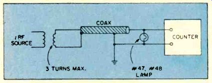
---------RF PROBE CIRCUIT
Three turns of number 18 gauge wire is fed by a suitable length of coaxial cable that is terminated in a number 47 lamp. This lamp will act as a 50 ohm termination for the coax. Such a scheme will work at the counters one megohm or 50 ohm input impedance sources.
PUTTING THEM TO WORK
Now let's look at a couple of practical applications of frequency counter techniques. You are a licensed technician and a citizen's band transceiver is brought to you because of claimed frequency deviation from the desired channels. All frequencies have been found to be in error by the user. The frequency counter can make your trouble shooting much easier.
First, using an RF probe and having the transmitter keyed, the frequencies of the various channels can be measured. If an error exists and the channels are 10 kilohertz apart, then the problem is not in the dividing circuit of the phase lock loop circuitry but rather in one of the harmonic oscillators. On the other hand, if the frequencies are not ten kilohertz apart, the problem is in the phase lock loop circuitry.
The proper probe for measuring the frequency of an oscillator consists of a voltage divider formed of two capacitors. If one uses a high impedance probe directly, the oscillator may be loaded down and a false reading obtained. As we have discussed, 10 millivolts are required for accurate counting. Since the impedance of a 21-foot long piece of 52-ohm coaxial cable combined with the input capacitance or shunting capacitance of the counter is a total of 100 picofarads, a 5 picofarad series capacitor will form a 1/20th voltage divider which should convert each volt of oscillator signal to a 50-millivolt signal across the input of the frequency counter.
If the problem is with the balanced mixer circuit, and the first IF frequency of the transceiver is known, the balanced mixer oscillator should be adjusted accurately to this frequency. If the problem is with the phase loop oscillator, then the reference oscillator should be checked and adjusted. By using these techniques, accurate frequency alignment can be made within 60 hertz with commonly available counters and 6 hertz in counters with temperature control units.
Another application would be to measure the frequency response of an audio amplifier. With a suitable low pass filter installed in series with the input probe, an inexpensive audio oscillator can be made of a pair of moderately priced operational amplifiers. The RC oscillator need not be calibrated since the frequency counter will serve as the reference for your measurements. A simple audio volt meter can then be used to measure the amplitude variation as a, function of frequency. The frequency counter therefore has allowed an inexpensive device to become a very accurate frequency generator.
Similar technique can be used to calibrate AM and FM receivers. Low cost oscillators can be made from UHF and VHF transistors or TTL circuitry. The output of these inexpensive RF sources is then fed into the frequency counter and circuit to be aligned. The accuracy of these frequencies is determined by the accuracy of the frequency counter. IF and RF frequency circuits can be aligned by monitoring the AGC voltage, audio output, or signal strength on the output meter of the receiver. This technique can also be used to evaluate and adjust sonar, depth finders, and fish finders. From the above discussion, it is clear that any inexpensive signal generator becomes a precision piece of equipment when it is used in conjunction with a frequency counter.
Frequency counters may also be used as signal detectors. Present day state-of-the-art devices have sensitivities in the order of 10 millivolts for signals of from six hertz to sixty megahertz. Therefore, they may be used to detect strong sources of RF radiation, trouble shoot individual oscillators in a given complex piece of equipment, or even detect the source of unwanted, spurious, or parasitic oscillations.
Thus, it is clear that a modern portable inexpensive counter is an indispensable tool to anyone interested in electronics. Considering their capabilities, frequency counters are a splendid "buy" and in kit form within the pocket range of most hobbyists. They are accurate, stable, sensitive, and compact, and their number of uses ate only limited to the imagination of their user. Creative designers and LSI circuitry have thus opened another door in the development of imaginative electronics.
=======