A Short Course in BASIC AC ELECTRICITY
The Editors of Electronics Theory Handbook present here a brief, compact course in basic AC electricity. No one basic course can be complete, but there is one that is undoubtedly the finest in existence today for those who wish to be self-taught on the subject. That course is contained within a complete major literary undertaking compacted into five volumes bearing the title `Basic Electricity/Electronics that is published by Howard W. Sams and Co., Inc.
Those portions appearing here were taken from Volume 2--How AC and DC Circuits Work.
Each chapter of the original work began with a section called "What you will learn," was followed by measured doses of facts to be learned, contained therein brief questions (and answers) to reinforce what was learned, and closing paragraphs, "What you have learned," that sums up the knowledge implanted in that chapter.
In no way could we hope to copy the style and scope of these chapters in the work that appears here.
Instead, we have condensed several chapters into one basic course with a quiz at the end (and answers) to present to you a portion of the basic AC electricity knowledge contained in the original work. Should the presentation style be to your liking, we suggest that you examine the entire Basic Electricity/Electronics series at a local bookstore. You could write to the book publisher directly and obtain a catalog of texts offered in which that series of volumes is included and described.
Now, to the short course that we present. Read it carefully even though you know the subject. It is an excellent refresher course, and it will reinforce your prior learnings.
-------- Basic Electricity/Electronics, five volumes, $11.95 each,
published by Howard W. Sams Company, Inc., 4300 West 62nd Street, Indianapolis,
Indiana 46268. Available at most quality bookstores in North America.
COPYRIGHT 1981 HOWARD W. SAMS COMPANY. INC.
========
BASIC AC CIRCUIT
The basic AC circuit is very similar to the basic DC circuit. The only difference is that an AC generator is used as a voltage source instead of a battery. In any AC circuit, the voltage shown at the generator in RMS voltage. The frequency shown is in Hertz, and the resistance is in ohms.
OHM'S LAW
Ohm's law, as you learned it for DC circuits, can also be used when AC is supplied to a resistive circuit. In a basic AC circuit, all calculations will be made with rms voltage and current values, unless other values are specified. Ohm's law also applies to peak values, but peak values are not generally very useful. Let us look at a basic AC circuit and see what happens as the switch is closed.
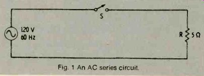
Fig. 1 An AC series circuit.
From Ohm's law, we find that the current in the above circuit will be I = 1;°= 24 amperes. But, since this is an AC circuit, we also know that both the 120 volts and the 24 amperes are rhms values; that is, they are the working values. Since AC voltage and currents appear as sinewaves, the voltage actually varies. The current also varies. See Fig. 2.
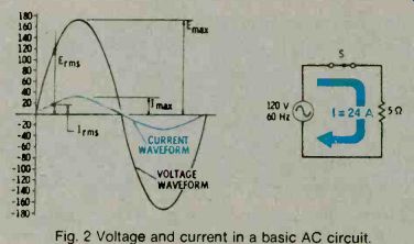
Fig. 2 Voltage and current in a basic AC circuit.
PHASE
When both the voltage and the current rise and fall together in exactly the same fashion, they are said to be in phase. When they do not, they are out of phase.
When an AC circuit contains only pure resistance, the voltages and currents will always be in phase.
When voltages and currents in an AC circuit are in phase, Ohm's law can be applied in the same manner as in DC circuits, provided you use the same kind of values (rms volts, etc.) for the voltages and currents.
POWER IN A BASIC AC CIRCUIT
Power is the work done by the current, and it is measured in watts. In DC circuits, you have seen how power equals the voltage multiplied by the current.
You also learned that the power in a resistance equals the value of the resistance multiplied by the current squared. However, voltage and current must be in phase if they are used together in an AC formula. For example, P = E x I is true only when voltage and current are in phase.
It is therefore a good idea when working with AC circuits to use only P = I2^R for finding power. When using this formula, it makes no difference whether the voltage and current are in phase or out of phase.
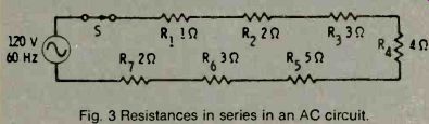
Fig. 3 Resistances in series in an AC circuit.
AC CIRCUITS WITH RESISTANCES IN SERIES
Fig. 3 is an AC circuit with its resistances in series. To find the current in this circuit, you must find the equivalent resistance of the resistors in series (the one resistance that can replace all the other resistances). This AC series circuit can be treated in the same way as a DC series circuit. Since the resistors are all in series, the equivalent resistance is the sum of all the resistances.
R_eq=R1 + R2 + R3 + R4 + R5 + R6 + R7
AC CIRCUITS WITH RESISTANCES IN PARALLEL
Fig. 4 is an AC circuit with its resistances in parallel.
The formula and solution for the equivalent resistance of the two resistors in parallel in Fig 4 is:
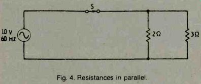
Fig. 4. Resistances in parallel
In an AC circuit with two equal resistances in parallel. The formula and solution for the equivalent resistance of the two equal resistors in parallel is:
Did you notice three important facts about parallel resistances?
1. The equivalent resistance is always smaller than either of the parallel resistances.
2. When two parallel resistances are equal, the equivalent resistance is one half as large as either resistance.
3. Frequency does not enter into the calculations.
Combinations of resistances can be simplified one step at a time. Fig. 5 gives an example of how to simplify a combination of parallel resistances.
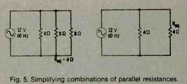
Fig. 5. Simplifying combinations of parallel resistances.
RESISTANCES IN SERIES AND PARALLEL
Now that you have learned how to handle resistors in series and pairs of resistors in parallel, it is easy to solve combinations of resistances by breaking them down into simple groups of resistors in series or pairs of resistors in parallel. Fig. 6 gives an example of how to break down a combination of series and parallel resistances.
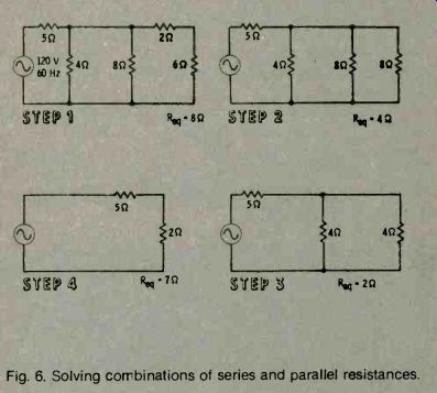
Fig. 6. Solving combinations of series and parallel resistances.
WHAT IS INDUCTANCE?
When current begins to flow in a conductor, a magnetic field builds up around it. As the magnetic field builds up, its expanding lines of force cut the conductor and generate a voltage that opposes the increasing current. This opposing voltage, or counter emf, is greater when the current is changing more rapidly. In fact, the counter emf is proportional to the rate of change of the current, but always opposes it.
When current is decreasing, the counter emf attempts to keep the current flowing.
When a sinewave current flows in an inductor (coil), the current is continually changing. Notice, in Fig. 7, that it is changing faster at the points where the sinewave crosses the zero line (points 1 and 3). It is not changing at all at the instant of each positive and negative peak (points 2 and 4).
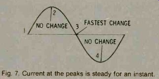
Fig. 7. Current at the peaks is steady for an instant.
The voltage in the inductor follows the rule just given. At point 1 in the illustration of Fig 8, the current is rising at its fastest rate. Therefore, the counter voltage, trying to keep the current from increasing, is at its negative peak. At point 2 on the wave, the current is not changing at all and, at this point, the counter voltage is zero. At point 3, the current is decreasing at its maximum rate, so the counter voltage, trying to keep the current from decreasing, reaches its positive peak. At point 4, the current is at its negative peak and is not changing at all. The counter voltage is zero.
We can follow the current sinewave waveform point by point and, at every instant, calculate its rate of change and the resulting counter emf. The resulting voltage waveform is another sinewave, but this one is 90° out of phase with the current. This is the waveform of the counter emf.
In order to keep the current flowing, and external voltage that is exactly equal but opposite to the counter emf must be applied. This is the applied emf, and it is 90° ahead of the current. We say that in an inductance, the current waveform lags the applied voltage waveform by 90°.
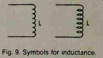
Fig. 8. Current lags the applied voyage by 90 deg.
In a DC circuit, inductance has an effect only when the direct current first starts to flow, and then again when you try to stop it. But, in AC circuits, the voltage is constantly changing and the inductance is constantly trying to retard the change in current. Fig. 9 illustrates the symbol for inductances.
Fig. 9. Symbols for inductance.
The unit of inductance is the Henry. A coil is said to have an inductance of 1 Henry if the current through it, changing at a rate of 1 ampere per second, encounters an opposition, or counter voltage, of 1 volt. This means that the opposition to current change shows up as a voltage opposing the applied voltage. All conductors have some inductance. Straight wires have very small amounts while coils have much more. In formulas, inductance is represented by the letter L. A coil or inductor is indicated on diagrams by one of the symbols shown in Fig. 10.
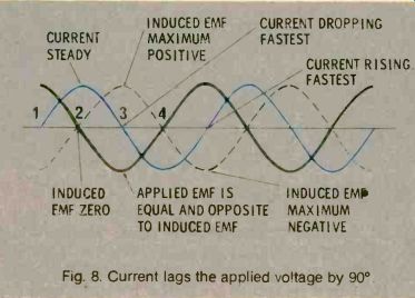
Fig. 10. Changing current produces a counter emf.
In part A of Fig. 10, with the current increasing at 1 ampere per second, a counter voltage of 1 volt appears and opposes the increase in current. In part B, as the current is decreasing, the inductive counter voltage of 1 volt is in a direction that tends to keep the current flowing. One Henry is a very large value of inductance. Therefore, inductances in milli-Henrys (mH) and micro-Henrys (pH) are more often found.
HOW DOES INDUCTANCE AFFECT AC CURRENT?
If a sinewave voltage is applied across a resistor, the current through the resistor also has a sinewave waveform. At every instant of the voltage waveform, the current is determined by Ohm's law and equals E/R. The two sinewaves, voltage and current, are exactly in step; they are said to be in phase.
Inductance resists a change in the current. But the voltage value in a sinewave is always changing and, therefore, as always trying to change the current through an inductance. This means that inductance acts at all times in an AC circuit and retards fie change in the current. This results in a current wave that is delayed after the applied voltage wave. The current wave lags the voltage wave by exactly 90°, or one quarter of the period of the sinewave waveform. The two waves are out of phase by 90°. See Fig. 11.
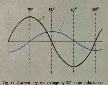
Fig. 11. Current bags the voltage by 90° in an inductance.
In a circuit containing only resistance, the voltage and current are in phase, and the voltage and current vectors have the same position. In a circuit having only inductance, the current vector is 90° behind the voltage vector (Fig.12). The length of each vector represents its magnitude.
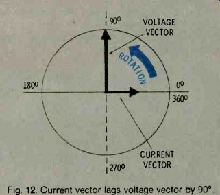
Fig. 12. Current vector lags voltage vector by 90°. Inductance, unlike
resistance, consumes no power.
When the current in the circuit is increasing, inductance takes energy out of the circuit. It converts this energy into a magnetic field. When the current in the circuit is decreasing, however, this magnetic field collapses, and all the energy returns to the circuit. Energy is borrowed, but none is used. Refer to diagrams in Fig. 13.
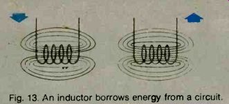
Fig. 13. An inductor borrows energy from a circuit.
FACTORS INFLUENCING INDUCTANCE VALUE
Several factors determine the amount of inductance in a coil. One of the most important factors is the number of turns in the coil. The inductance of a coil is proportional to the square of the number of its turns.
This means that if a certain coil has twice as many turns as another coil, it will have four times as much inductance. If it has three times as many turns, it will have nine times as much inductance, etc. The diameter also affects the inductance of a coil. The larger the diameter, the more inductance it will have.
Placing an iron core in the center of a coil is another way to increase inductance. A coil wound on an iron rod has much more inductance than an air-core coil.
This is because an iron core can sustain a much greater magnetic field than air and, as you have learned, the inductance of a coil is related to the amount of magnetism it can produce.
INDUCTANCE AND INDUCTION
Inductance is closely related to induction. Inductance is a circuit property. Induction, on the other hand, is the interaction between an electric current and a magnetic field. Whenever a current flows in a conductor, it sets up a magnetic field around the conductor. See Fig. 14.
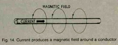
Fig. 14. Current produces a magnetic field around a conductor.
A good way to remember the direction of an induced magnetic field is the left-hand rule. With your left hand grasping the wire and your thumb pointing in the direction of the current, the curved fingers of your hand indicate the direction of the field. The direction of the magnetic field is always the direction toward the north-seeking pole of the magnet.
A coil with a direct current flowing through it in a particular direction acts as a magnet with a fixed polarity, just as if it were a bar magnet. When the current is AC instead of DC, the polarity of the magnetic field alternates in the same manner as the current. Conversely, if an electrical conductor is moved through a magnetic field (Fig. 15), an electric current is induced in the conductor. This is the principle that causes generators to work.
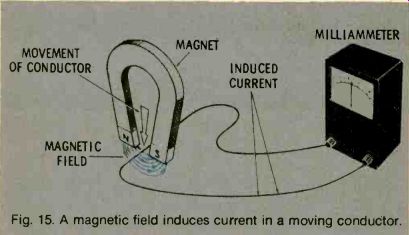
Fig. 15. A magnetic field induces current in a moving conductor.
If a coil is connected to an ammeter and a bar magnet is moved through the coil (Fig. 16), the ammeter will show that an electric current flows. This current is induced by the magnetic field only. If you move the bar magnet back and forth through the coil continuously, the induced current will be an alternating current. Use the lowest amperage range on the multimeter for this experiment.
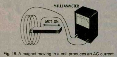
Fig. 16. A magnet moving in a coil produces an AC current.
INDUCTIVE REACTANCE
When current in an inductor is changing, inductance opposes the change by generating a counter emf. In a DC circuit, this effect is present only at the time that a switch is being closed or opened, and it dies away in a few moments. In AC circuits, however, current is constantly changing, so inductance is constantly acting to oppose it. The faster the current changes, the more opposition there will be. Obviously, the higher the frequency of a current, the faster the current will change. Inductance, therefore, tends to offer more opposition at high frequencies than at low frequencies.
In an AC circuit, this reaction to a changing current is present in addition to ordinary resistance. This opposition to the flow of an AC current through an inductor is called inductive reactance. The greater the inductance of the circuit, the greater is the inductive reactance. Inductive reactance does not oppose the flow of DC current (zero frequency). The more rapidly the current is changing, the greater the opposition, or inductive reactance, will be. Since the rate of change in the current depends on the frequency of the current, the higher the frequency is, the greater will be the opposition to current flow.
The symbol for inductive reactance is XL. Inductive reactance (XL) is measured in Ohms, as resistance is (but don't confuse the two). The formula for inductive reactance is:
XL = 2 pi fL
where, XL is the inductive reactance in Ohms, pi equals 3.14, f is the frequency in Hertz, L is the inductance in Henrys.
From the formula, it is apparent that XL increases with frequency. When the frequency is doubled, XL doubles. Why is this? Because when the frequency is doubled, the current is reversing twice as fast, and the opposition to this change (caused by the inductance) also doubles. Notice, too, that if the frequency in the formula is equal to zero, inductive reactance disappears completely. A DC current has zero frequency and is not affected by inductance.
Inductance is very useful because every inductive circuit is frequency sensitive. This principle is used in filters, antennas, and many other applications. It means that an inductive circuit passes direct current and low-frequency alternating current, but it impedes the higher frequencies.
APPLICATION OF INDUCTANCE
Because inductive reactance depends on frequency, inductance is often used in filters. Filters are special circuits that have the property of allowing certain frequencies to pass while blocking others.
There are, for example, low-pass filters which pass low frequencies and block high ones, and bandpass filters which pass only a certain band of frequencies. The following are two simple filters that depend only on inductance. The first one, which has an inductance in series, blocks high frequencies (Fig.17). It is a lowpass filter.
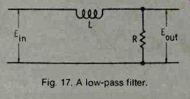
Fig. 17. A low-pass filter.
The second circuit has an inductance in parallel, or across it. This inductance will bypass the low frequencies (Fig. 18). As the frequency increases, voltages across the inductor increases. Therefore, there is more output voltage at high frequencies, and the circuit acts as a high-pass filter.
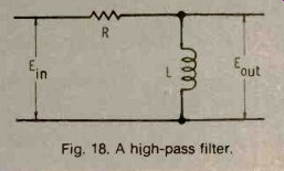
Fig. 18. A high-pass filter.
TRANSFORMERS
You are now aware that a moving magnetic field generates an electric current in a conductor, and also that current flowing in a conductor produces a magnetic field. These two effects can be combined in a circuit such as in Fig 19. One coil has a current flowing in it. It is an AC current that sets up an alternating
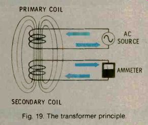
Fig. 19. The transformer principle.
magnetic field in and near the coil. If another coil is placed next to it, there will be a second alternating current induced in the second coil. The first coil is the primary coil, the second coil is the secondary coil, and the combination of the two is a transformer. Most commercial transformers appear as shown in Fig. 20.
PRIMARY SECONDARY
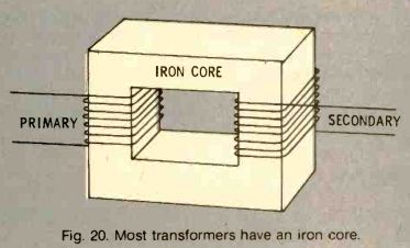
Fig. 20. Most transformers have an iron core.
An iron core is used to increase the magnetic flux and to channel it to the secondary coil. The primary coil sets up a magnetic field in the core, and the secondary coil converts the field back to electric current. Power is actually transferred from the primary to the secondary. A lamp or other load placed in the secondary circuit will operate.
One of the main advantages of using transformers is that they can change voltage. They do this because the voltage induced in the secondary depends on the number of turns in the secondary as compared to the number of turns in the primary coil. If the turns in the secondary are doubled, the induced voltage will be doubled (but no more power. because the current will be halved). The voltage ratio of the secondary to the primary is the same as the turns ratio. So, if the primary of a transformer has 1000 turns and the secondary has 100 turns, it is step-down transformer because it steps down the primary voltage by 10 (1000/100). If the connections are reversed, it becomes a step-up transformer with the same ratio.
INDUCTIVE CIRCUITS
A good way to understand circuits containing inductance is to work through a simple problem. For example, the illustration in Fig. 21 shows a schematic of a basic inductive-reactance AC circuit. Assume that the resistance in the leads and the coil is negligible.
The problem is to find the rms value of the current in this circuit. Ohm's Jaw still applies.
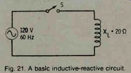
Fig. 21. A basic inductive-reactive circuit.
You have learned that power in a circuit is: P = EI
...where E is the voltage and I is the current.
With a sinewave waveform, the power at any time during the cycle is the product of the voltage and the current at that moment (Fig. 22). In a resistive circuit, power has a pulsating waveshape.
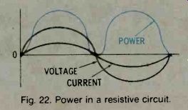
Fig. 22. Power in a resistive circuit.
You have already learned that no power is dissipated in a circuit that contains only inductance. A look at the waveforms in Fig. 23 will help you understand this. Between points B and C, both current and voltage are positive. If you multiply their values, it appears that power is being dissipated exactly as in a resistive circuit. Between points D and E, both current and voltage are negative, and again you have exactly the same situation as in a resistive circuit-power appears to be dissipated. But, between points A and B and points C and D, there is a situation that never exists in a resistive circuit.
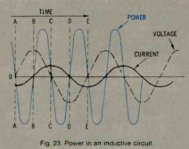
Fig. 23. Power in an inductive circuit.
As you can see, there are pulses of negative power as well as positive power. The positive-power pulses represent the time when the circuit is utilizing power to produce a magnetic field. The negative-power pulses represent the time when the circuit is absorbing power from the magnetic field. The negative pulses and the positive pulses are equal and cancel each other, so the total power dissipated is zero. Two important rules that you must remember are:
When you multiply positive values by positive values, or negative values by negative values, the results are positive values.
When you multiply positive values by negative values, the results are negative values.
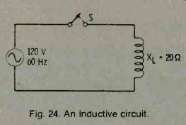
Fig. 24. An inductive circuit.
Inductive reactance in a circuit changes with frequency, but inductance stays the same. To find how the circuit in Fig. 24 behaves at other frequencies, you must determine the inductance. Use the formula:
L =2f (this is a form of XL = 2 pi-fL)
Inductors in Series
The simplest form of a series inductive circuit is one with two inductors in series. To find the current in the circuit of Fig. 25, and XL, and XL2, and then use Ohm's law with the equivalent XL.
If the value of each inductance (L) is known, add the individual inductances to find the total inductance and then calculate XueQ for the circuit.
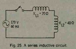
Fig. 25. A series inductive circuit.
PARALLEL INDUCTIVE CIRCUITS
A circuit containing pure inductances in parallel can be treated much like a parallel resistance circuit. The simplest parallel circuit in Fig. 26 can be solved using the formula:
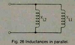
Fig. 26 Inductances in parallel.
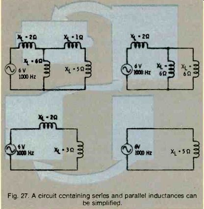
Fig. 27. A circuit containing series and parallel inductances can be
simplified.
As with resistance, the equivalent inductive reactance of two inductors in parallel is always smaller than that of either single inductor. Combined series and parallel circuits, or large groups of inductors in parallel, can be simplified in steps by using the same method that you used with resistances. Refer to Fig.
An RL circuit is one that contains both resistance and inductance. You are more likely to encounter circuits of this sort than pure inductive circuits or pure resistive circuits. In fact, even the connecting conductors in a circuit have some inductance, and every coil has some resistance.
It is sometimes important to know how "good" or how "pure" the inductance of a coil is. This quality is usually measured with a factor called Q. This is simply a ratio, Q = Ru. With a large Q, the power loss in the coil will be small, and the inductance will be more efficient. Notice, however, that Q varies with frequency, because the inductive reactance varies. For example, a coil with an XL value of 5000 Ohms at 10,000Hz and a DC resistance of 50 Ohms will have a Q at that frequency of 100 (5r). If this same coil is used at 5000 Hz, its inductive reactance will only be 2500 Ohms, and its Q will equal 50 (2550°°).
TIME CONSTANT
A different method that is used to measure the relative amounts of resistance and inductance is a very important factor when dealing with pulse circuits. The shape of a pulse is changed by inductance.
When a pulse is passed through an RL series circuit, the roundness of the current rise and the time it takes for the current to rise to its final value depend on the amounts of inductance and resistance in the circuit.
As you would expect, the greater the value of inductance, the slower the current will build up. At the same time, the resistance in the circuit has the opposite effect-the smaller the resistance, the longer the current takes to reach the steady-state conditions.
See Fig. 28. (The reason is that when the resistance is smaller, the final current will be larger, and it will therefore take longer to reach the final value.)
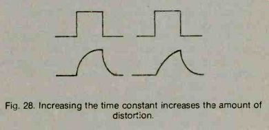
Fig. 28. Increasing the time constant increases the amount of distortion.
When dealing with filters and pulse circuits, circuits containing L and R in series are often described by their time constant. This is a measure of how quickly the current in the circuit reaches its final peak value.
The time constant equals UR and is expressed in seconds. If a circuit has an UR time constant of one half second, the current will reach 63% of its maximum (peak) value in one-half second when a voltage is applied to the circuit. See Fig. 29.
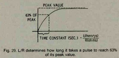
Fig. 29. L/R determines how long it takes a pulse to reach 63% of its
peak value.
PHASE
It has been previously explained that AC voltage and current are always in phase in a purely resistive circuit and that AC current through an inductance always lags the applied voltage by 90°. When resistance and inductance are combined in a single circuit, the amount of phase difference between the current and voltage depends on which (resistance or inductance) has the greater value; that is, it depends on the Q of the circuit.
If the applied voltage has a sinewave waveform, the current through an RL circuit will also have a sinewave waveform. Therefore, you can think of it as being Fig. 30. One current vector can represent the combined effect of resistive and inductive currents.
generated by a rotating current vector. However, this vector is a combination (or resultant) of the resistive and inductive current vectors. As you see in Fig. 30, these two vectors form the two sides of a rectangle, and the overall (resultant) current vector is the diagonal of the rectangle. The angle labeled with the symbol O is the phase angle, the number of degrees by which the overall current lags voltage.
IMPEDANCE
To find the current flowing in a purely inductive circuit, you apply Ohm's law , using inductive reactance instead of resistance (I = E/XL). Inductive reactance, of course, equals 2 pi fL and varies with frequency and inductance.
What happens when both resistance and inductance are in series in the same circuit? Say, for example, that the resistance is 3 Ohms, and the inductive reactance (for a specific frequency) is 4 Ohms. As you know by now, the current through the resistance in an AC circuit is in phase with the applied voltage, while the current in the inductance lags 90° behind the voltage. Just as the rms value of the resistive current cannot be added to the rms value of the inductive current to find the overall current, the 3 Ohms of resistance cannot be added to the 4 Ohms of inductive reactance. Instead, the overall effect of the two must be found in the same way that the overall current vector is found. The overall effect of resistance and reactance working together is called impedance.
The symbol for impedance is Z.
RELATIONSHIP OF XL, R, AND Z
One simple way to find the overall effect of 3 Ohms of resistance and 4 Ohms of inductive reactance is to draw a line 4 units long pointing downward. This line represents the inductive reactance. Then draw a line 3 units long at right angles to the first line. This line represents the resistance. The two lines form two sides of a rectangle. The diagonal of the rectangle will represent the impedance.
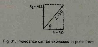
Fig. 31. Impedance can be expressed in polar for Notice the angle
between R and XL vectors. This angle is usually indicated by the Greek
letter theta and is referred to as the phase angle.
It is not enough to say that a circuit has an impedance of 5 Ohms; you must also know the angle by which the current and voltage are out of phase.
There are two ways to do this. You can express impedance in polar form, ZZO. In the example in Fig. 31, Z is 5. Or, you can express the impedance as the sum of 3 Ohms resistance plus 4 Ohms inductive reactance. A short way of saying this is 3 + j4. The j tells you that the 4 is 90° ahead of the 3. In general, Z = R + jXL. This is the rectangular form of impedance. Although you can find impedance by drawing vector diagrams and measuring, there are other ways of finding the value of impedance.
As long as 8 remains the same, the proportion between reactance and impedance will be the same.
The proportion between resistance and impedance and between reactance and resistance will always be the same.
When any two facts about a combination of XL and R are known, the other facts can be found by using a table of trigonometric functions. Some trigonometric relationships of XL, R, and Z are given in Fig. 32.
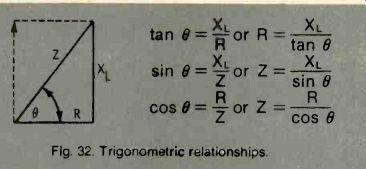
Fig. 32. Trigonometric relationships.
Using the relationships shown in Fig. 32. the impedance of an inductive circuit, for which XL is 7 Ohms and R is 10 Ohms, can be found.
(You will need a trigonometric table for this calculation.)
Determining the impedance of the circuit in Fig. 33.
To do so requires the summing of resistors and inductors first.
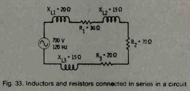
Fig. 33. Inductors and resistors connected in series in a circuit.
WHAT IS CAPACITANCE?
Capacitance is the property of an electrical circuit that opposes a change in voltage. Capacitance has the same reaction to the voltage that inductance has to current. This means that if the voltage applied across a circuit is increased, capacitance will resist that change.
If the voltage applied to a circuit is decreased, capacitance will oppose the decrease and try to maintain the original voltage.
In a DC circuit, capacitance has an effect only when voltage is first applied, and then again when it is removed. Note that current cannot flow through a capacitance. However, an AC current appears to flow through a capacitance-you will learn how later. Since voltage is constantly changing in AC circuits, capacitance acts at all times to retard these changes in voltage.
A basic capacitor (sometimes called a condenser) is shown in Fig. 34. It consists of two conducting metal plates separated by a layer of air or other insulating material, such as paper, glass, mica, oil, etc. The insulating layer is called the dielectric.
Ali capacitors have two plates and a separating layer. In practice, these are often stacked or even rolled into a compact form.
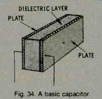
Fig. 34. A basic capacitor.
When a capacitor is first connected to a battery, electrons from the negative terminal of the battery flow to the nearest capacitor plate and remain there. They can go no farther, since the second plate is separated from the first by an insulating layer. Electrons are moved from the opposite capacitor plate and flow into the positive terminal of the battery. After this initial movement of electrons_ one plate is filled with all the
[...]
HOW DOES CAPACITANCE AFFECT AC CURRENT?
Although current cannot flow through a capacitor, an AC current appears to do just that. The reason lies in the nature of capacitance. If the voltage across the plates is continuously varied, the number of electrons on one plate of a capacitor repels electrons from the other plate. Decreasing the number of electrons on the first plate allows electrons to be attracted back to the other plate (Fig. 35). Thus, an AC voltage can, in effect, get across the dielectric; since the voltage is alternating, it causes an AC current on the other side of the dielectric. In other words, voltage changes are transmitted across the gap.
If a capacitor has the same voltage as the applied voltage, no current will flow to or from it. However, if the applied voltage changes, the capacitor voltage will no longer equal the applied voltage. Current will flow trying to equalize the two voltages. In a circuit, this means that if an AC sinewave voltage is applied across a capacitor, an AC sinewave current will appear on the opposite side, even though no electrons cross the dielectric layer.
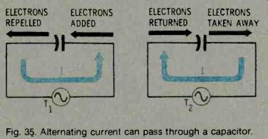
Fig. 35. Alternating current can pass through a capacitor.
PHASE
Just as with inductance, current and voltage are not in phase in a capacitive circuit (Fig. 36). The voltage lags the current (current leads the voltage) by 90°. Fig. 36. Current leads voltage in a capacitor.
At any instant, the current flowing into or out of a capacitor is proportional to the rate of change of the applied voltage. This can be seen in the illustration given in Fig. 37. The applied voltage is changing most rapidly at time A, the beginning of the sinewave cycle.
Therefore, the current is maximum. At time B, the voltage across the capacitor has reached its peak and for the moment, is not changing. Therefore, current at this instant is zero. At time C, voltage across the capacitor again is changing quite rapidly (but in the negative direction) and, so, the current is at its negative peak. At time D, when the voltage reaches its negative peak and is momentarily not changing, the current waveform passes through zero once more. If we trace the current from point to point along the voltage waveform, the result is a sinewave, but one that leads the voltage by exactly 90°. Thus, if the voltage across the capacitor is a continuous sinewave voltage with a constant amplitude, the current through the capacitor circuit has a sinewave waveform that is 90° ahead of the voltage waveform. Refer to Fig. 37.
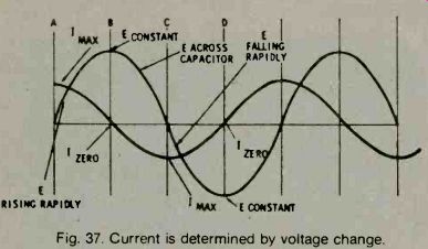
Fig. 37. Current is determined by voltage change.
Thus, current and voltage vectors in a capacitive circuit are 90° out of phase. In the illustration given in Fig. 38, the current vector is ahead of the voltage vector by 90°.
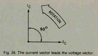
Fig. 38. The current vector leads the voltage vector.
FACTORS AFFECTING CAPACITANCE VALUE
The amount of electrical charge that can be stored in a capacitor (the number of electrons that can be placed on the plate) varies with the area of the plates.
Consequently, capacitance varies directly with area if area is doubled, the capacitance is doubled. When the area is doubled or twice as many plates are connected in parallel, there is twice as much area to store electrons, and the capacitance is therefore twice as great. See Fig. 39.
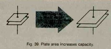
Fig. 39. Plate area increases capacity.
Capacitance can also be increased by placing the plates closer together. When the plates are closer, the attraction between the negative charges on one side and the positive charges on the other side is greater, and thus more charge can be stored. It is, of course, necessary to keep the plates far enough apart so that the charge does not cross the gap. See Fig. 40.
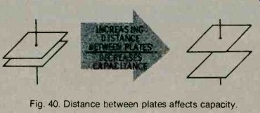
Fig. 40. Distance between plates affects capacity.
Higher values of capacitance can be obtained by using an insulating material (dielectric) other that air.
This allows the plates to be placed closer together without permitting the charge to cross the gap.
Dielectrics such as mica, glass, oil and Mylar are a few of the materials that can sustain a high electric stress without breaking down. This property is called the dielectric constant. See Fig. 41. The higher the dielectric constant is, the better is the dielectric. Air has a dielectric constant of 1, glass about 5, and mica 2.5 to 6.6.

Fig. 41. Dielectric material affects capacity.
CAPACITIVE REACTANCE
Like inductance, capacitance has a reactance-an opposition to the flow of alternating current. But capacitive reactance decreases as frequency increases.
Suppose a capacitor is connected in series with an alternating voltage source. There is no resistance in the circuit. Because the circuit in Fig. 42 contains no resistance, the voltage across the capacitor will be the same value as the source voltage at every instant.
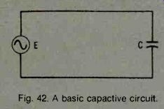
Fig. 42. A basic capacitive circuit.
When a capacitor is charged up to voltage E, it stores an amount of energy equal to the capacitance times the voltage. If the peak voltage of the AC source is E, the capacitor will have stored a particular amount of energy every time the voltage sinewave hits its peak, and again stores that amount whenever the voltage reaches its negative peak. Refer to Fig. 43. The energy depends only on capacitance and peak voltage.
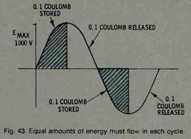
Fig. 43. Equal amounts of energy must flow in each cycle.
What happens when the frequency of the power source is doubled? If the peak voltage (E) is unchanged, the capacitor will charge every half cycle to the same amount as before. But, it will have to do this twice as fast because the frequency is doubled. This means that the same amount of energy must flow into the capacitor in only half the time. See Fig. 44. And, since the voltage is the same, we must have twice the current to supply this same amount of total energy.
What does this mean? The frequency was doubled, and this doubled the current flowing into the capacitor--yet, the input voltage remained the same. A pure capacitance lets twice as much current flow if the frequency is doubled.
Capacitive reactance is the opposition that pure capacitance offers to the flow of current. It is expressed in Ohms, and its symbol is Xc Capacitive reactance depends on frequency. As the frequency increases, the rate of change of applied voltage increases, and the current also increases. As the frequency is reduced, the rate of change of the voltage goes down, and less current will flow.
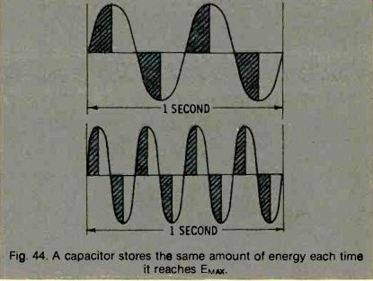
Fig. 44. A capacitor stores the same amount of energy each time it reaches
EM,ix.
At this point, you can more easily see why capacitor current leads the voltage across the capacitor. It is necessary for the capacitor to charge up to the given voltage, and this charging is done by the current.
Hence, the charging current will reach its maximum value at the time the charging is going on at the greatest rate; that is, when the rate of change of voltage is the most rapid.
As the capacitor approaches full charge, the voltage rate of change slows down, and the current decreases.
When the capacitor is fully charged and its voltage has reached maximum, there is no charging current flowing-that current has already dropped to zero at this time. A similar process occurs during discharging.
At all times, current leads the voltage by 90°, or one quarter of the cycle. In a steady-state AC situation, when the applied voltage has a sinewave waveform, both voltage and current will have sinewave waveforms.
Capacitive reactance depends on frequency. Since it lets more current flow as the frequency increases, capacitive reactance must decrease as the frequency increases. It also depends on the size of the capacitance. As capacitance increases, more current must flow into the capacitor to charge it to the same voltage (since the amount of energy stored equals C X E). As a result, capacitive reactance decreases when capacitance increases. The formula for capacitive reactance is :
Xc = 2 pi fC
ohms where, f is the frequency in Hertz, C is the capacitance in Farads.
Capacitive reactance can be used in calculating current in a purely capacitive circuit with the use of Ohm's law.
A BASIC CAPACITIVE CIRCUIT
First, let's review what you have learned about capacitance by applying it to the basic capacitive circuit shown in Fig. 45. You have already learned that when a sinewave AC voltage is applied, the current in a capacitor always leads the voltage by 90°. You have also learned that a capacitor consumes no power; all the energy it takes out of a circuit in one quarter cycle is returned in the next quarter cycle.
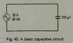
Fig. 45. A basic capacitive circuit.
Both of the above statements are true, not only for a single capacitor, but also for any combination of capacitors. In fact, any circuit that contains only pure capacitances, no matter how many capacitances it may have, it will behave as if it were one capacitor.
CAPACITORS IN PARALLEL
Capacitors add in parallel. See Fig. 46. It is easy to understand why this is true if you remember that the more plates a capacitor has, the greater is its capacitance. If two capacitors are connected in parallel, you can find their equivalent capacitance just by adding their values. If a 200-pF and a 400-pF capacitor are connected in parallel (see Fig. 47), the equivalent capacitance of the combination is 200 pF plus 400 pF, or 600 pF. This is also true with three, four, or any other number of capacitances connected in parallel.
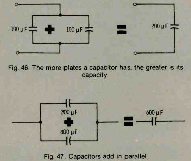
Fig. 46. The more plates a capacitor has, the greater is its capacity.
Fig. 47. Capacitors add in parallel.
CAPACITORS IN SERIES
If two capacitors are connected in series (see Fig. 48), what is their equivalent capacitance? We cannot simply add C1 and 02 together. Instead, we use the relationship:
What is the total capacitance of 200 pF and 400 pF connected in series? Using the above relationship, the total capacitance is calculated to be:
Notice that this equivalent value is smaller than either of the individual capacitor values.
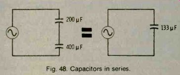
Fig. 48. Capacitors in series.
Complicated circuits can be simplified by analyzing them in steps as shown in Fig. 49.
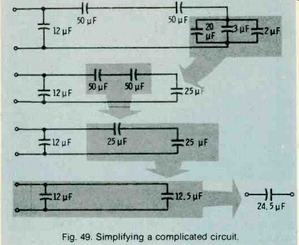
Fig. 49. Simplifying a complicated circuit.
On the preceding pages, capacitance values were combined, not capacitive-reactance values. You must not confuse the two. To combine capacitive-reactance values, whether in series or in parallel, use the same rules that apply to resistance-add series values and combine parallel values by use of the formula:
X1 XX2 Xeq X1 + X2
RC CIRCUITS
Actually, an entirely pure capacitance does not exist. The leads of capacitors have some small value of resistance. Also, the dielectric layer is never quite perfect; it has some extremely high value of resistance.
So, if you wanted to be very accurate, you would represent these unwanted resistances by inserting their values in your circuit diagram, and treat them just as if they were actual resistors. For the most practical purposes, however, you can disregard them.
Now let's see what happens if we put capacitors and resistors in the same circuit. As you already know, we cannot add resistance and capacitance, because they are two different quantities (resistance is measured in Ohms, capacitance in Farads). Instead, it is necessary to use capacitive reactance, which you learned about in the previous chapter. However, just as with inductance, in order to add resistance to capacitive reactance, it must be remembered that a resistive current is in phase with the voltage, while a capacitive current leads the voltage by 90°. So the two cannot be added directly-they must be added vectorially (Fig. 50).
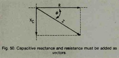
Fig. 50. Capacitive reactance and resistance must be added vectors.
IMPEDANCE
The capacitive-reactance vector is 90° behind the resistance vector in Fig. 50. The resulting quantity, impedance, is somewhere between the two, and its length (quantity) is the diagonal of the rectangle they form. This is capacitive impedance, which is different from inductive impedance because it lags the resistance vector. The way to write capacitive impedance is R jX°; the minus sign tells the story. All inductive impedances are represented by a + j and all capacitive impedances by a j in front of the X. If you have a table of trigonometric functions, you can get a more accurate measurement of impedance, using the same formulas that you used to find inductive impedance. Remember, these formulas apply to both inductive and capacitive impedance.
RC TIME CONSTANT
The ratio between R and C has an important effect on the characteristics of a circuit. The way this ratio affects AC voltage and currents is indicated by a time constant in much the same way that the effects of combined inductance and resistance were indicated.
What happens if you apply a pulse, such as a square wave, to a series RC circuit? See Fig. 51. The capacitor will oppose the sudden change of voltage and will gradually charge to source voltage E. The rate of charge (the initial current that will flow) is limited by resistance R. In fact, the initial current will be I = E/R and will gradually decrease to zero as the voltage builds up across the capacitor.
APPLIED VOLTAGE
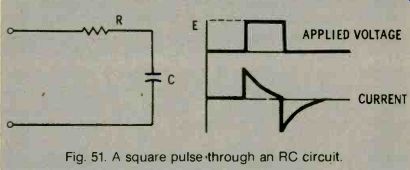
Fig. 51. A square pulse through an RC circuit.
CURRENT
The voltage across the capacitor will start at zero and will build up smoothly until it equals source voltage E. The voltage across the resistor will, at any instant, equal the difference between the source voltage and the voltage across the capacitor; it will also be a spike as shown (Fig. 52).
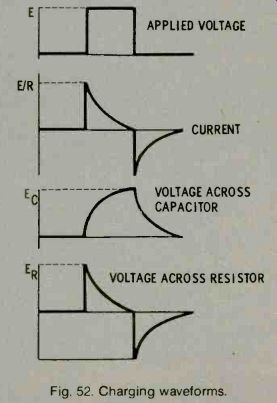
Fig. 52. Charging waveforms.
The rate of charging-the steepness of the capacitor voltage curve-depends on how much current the resistor will allow to flow. The higher the resistance, the less the current flow and the slower will be the charging rate. This fact is expressed in numbers by the time constant of the circuit. The time constant of a series RC circuit is simply R x C, where R is Ohms, C is in Farads, and the time constant is in seconds. RC is the time it takes the capacitor to charge to 63.2% of the source voltage. For example, if R is 10,000 Ohms and 10 C is 10 micro-Farads, RC is 10,000 X 1,000,000 = 0.1 second.
When a capacitor has been charged, it actually contains a certain amount of stored energy. The stored energy is C times E coulombs, where C is the capacitance in Farads and E is the voltage to which the capacitor is charged.
If a charged capacitor is connected in a circuit, its stored energy is released into the circuit. An example of this is a battery-capacitor photographic-flash circuit. Capacitor C is charged up to the battery voltage by throwing the switch to position A (Fig. 53A). The rate of charge depends on the resistance in the battery circuit (wire resistance and the internal resistance of the battery). When a flash is desired, the switch is moved over to position B (Fig. 53B). The capacitor,
which is charged to full battery voltage (E), has not opposing voltage in the new circuit, and its discharge is limited only by the resistance of the flash bulb. The stored energy flows through the flash bulb and, in doing so, fires the bulb. The discharging current follows the curve shown in the figure; again, the speed of discharge depends on the time constant of the circuit.
(A) Charging from battery.
(B) Discharging through bulb.
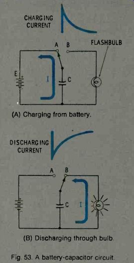
Fig. 53. A battery-capacitor circuit.
An RC series circuit can be used as a timing device.
See Fig. 54. It is, in fact, often used this way (e.g., in television receivers). In the circuit of Fig. 54, the length of time that it will take for the capacitor voltage to rise to some given value can be calculated. If some device (which will be triggered only when this given value of voltage is reached) is connected across the output terminals B, the device (such as a gas diode) will be triggered after a predictable time delay from the time that the input voltage (E) is applied.
The length of the time delay can be controlled by varying either the resistance or the capacitance. However, if the amount of energy stored is important, the delay can only be varied by changing the resistance.
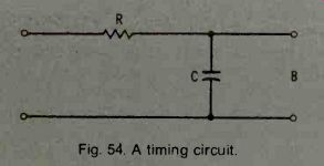
Fig. 54. A timing circuit.
RLC IMPEDANCE
When vector diagrams are used to find the impedance and phase angle (as in the previous chapters), +jXL is always drawn upward, while -jXc is always drawn downward. This leads to the idea that inductance and capacitance provide opposite reactions.
What happens if a circuit contains both inductance and capacitance in series? The two reactances cannot be just arithmetically added to find the total reactance.
+jXL and -jX, tend to offset each other, and the total effect is their difference.
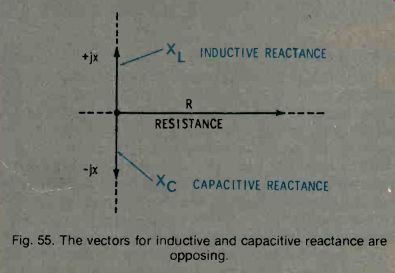
Fig. 55. The vectors for inductive and capacitive reactance are opposing.
This difference is in the direction of the greater of the two reactances (Fig. 55). So, if a circuit contains a capacitor, the reactance of which is -j50 Ohms, and an inductor, the reactance of which is +j100 Ohms, the net result is equivalent to an inductive reactance of +j50 Ohms. A series circuit containing L and C behaves either as a capacitor or as an inductor, depending on whichever of the two components has the greater reactance at the operating frequency.
If a resistor is connected in series with an LC circuit, the impedance of the circuit will simply be the resultant reactance (whether inductive or capacitive) in series with the resistor.
RESONANCE
A special case arises when the capacitive reactance and the inductive reactance are equal. When this condition exists, the reactances cancel each other and the circuit appears to be purely resistive. This can happen at only one frequency, however, for each particular set of inductive and capacitive values. At a low frequency, the inductive reactance is low an the capacitive reactance is high. The circuit, therefore, behaves as a capacitance. If the frequency of the applied voltage is gradually increased, the inductive reactance will gradually decrease. At some point, the two reactances become equal, and thus cancel. This point is called the resonant frequency of the circuit. If the frequency is increased further, the inductive reactance becomes greater than the capacitive reactance, and the circuit will behave as an inductor.
Every L and C combination has one, and only one, resonant frequency. It is the frequency at which the inductive and capacitive reactances are equal (Fig. 56).
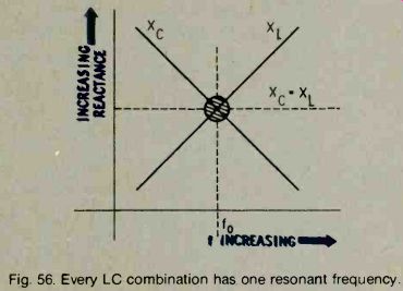
Fig. 56. Every LC combination has one resonant frequency.
RESONANT FREQUENCY CALCULATION
The resonant frequency (fo) formula is derived as follows:
Multiplying by fo,
Dividing by 2rrL, 2rrf0L = 1 2771 oC 2rrf02 L = 277C z__ 1 fo 4rr2LC
Taking the square root of both sides,
fo = 1 2rrx/ LC
Q OF A RESONANT CIRCUIT
At resonance, the voltage across the capacitor and across the inductor is greater than at any other frequency. See Fig. 57. The effective current in the circuit is also higher at the resonant frequency than it is below or above resonance.
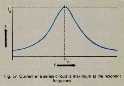
Fig. 57. Current in a series circuit is maximum at the resonant
frequency.
The quality of a resonant circuit can be measured by the O factor. The Q of a circuit is the ratio of the energy stored in the capacitor and inductor divided by the energy dissipated in the resistor.
The amount of reactive opposition to current flow at a specific given frequency in not affected by the Q of the circuit. The resistive opposition, however, does vary according to the Q factor. This means that the shape of the resonance curve depends on this factor. If the frequency is changed from fo to a frequency where the reactance is low, and if the Q is high (resistance is only a few Ohms), the total impedance will be halved.
If the Q is low (resistance is high), the total impedance will be increased by only a small amount, and the current decrease will be very small. The Q factor determines the exact shape of the resonance curve of a circuit. For example, if the resonant frequency is multiplied by 1/Q, and if the frequency of the input signal is changed from the resonant frequency by this amount, the current will be 0.707 times the resonant current. However, if the frequency is changed by ½ Q times the resonant frequency, the current will be 0.447 times the resonant current. Refer to Fig. 58.
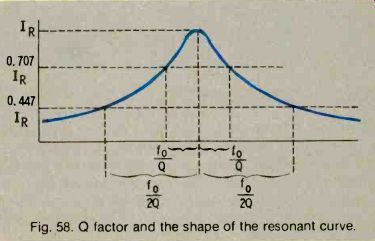
Fig. 58. Q factor and the shape of the resonant curve.
APPLICATIONS
Frequency-selective properties of series resonant circuits are useful in applications where it is desired to pass one particular frequency with more ease than others. Thus, the circuit can act as a filter. Refer to Fig. 59.
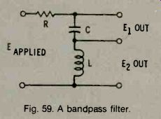
Fig. 59. A bandpass filter.
If the voltage across either L or C is used for the output, the voltage will be much greater for signals having the resonant frequency than for signals above or below this frequency. Such a circuit is called a bandpass filter. The width of the bandpass depends on the circuit Q-the higher the Q, the sharper the resonance curve and the narrower the bandpass.
In a radio-frequency circuit, a high-Q tuned circuit can be used to select the desired station and reject all others. In a power supply, a circuit using fairly large L and C values may be used to reject undesired frequencies.
PARALLEL RESONANT CIRCUITS
A parallel resonant circuit is made up of inductance and capacitance (see Fig. 60) so that each of the two branches shows reactance. The capacitive losses are usually associated with the coil rather than with the capacitor. The resistance is usually shown as being in series with the inductance.
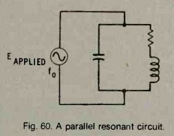
Fig. 60. A parallel resonant circuit.
PARALLEL RLC CIRCUITS
When an AC voltage is applied to a parallel RLC circuit, each of the two branches shows reactance.
The capacitive reactance in the capacitor branch is high at low frequencies, and decreases as the frequency increases. Similarly, the inductive reactance of the inductor branch is low at low frequencies, and increases as the frequency increases.
The capacitor has a high reactance and the inductor a low reactance at frequencies below resonance.
Consequently, most of the current flows through the inductive branch and lags the applied voltage. Similarly, if the frequency is above resonance, most of the current will flow in the capacitive branch and will lead the applied voltage.
At some particular frequency, the two reactances in a parallel resonant circuit are exactly equal. Since there is an AC voltage applied across each branch, both kinds of current are present-an inductive current in the inductive branch and a capacitive current in the capacitive branch. At resonance, the two currents are equal. But because one of the current leads the applied voltage by 90° and the other lags the voltage by 90°, the two currents are 180° out of phase with each other. This means that they cancel (add up to zero). See Fig. 61.
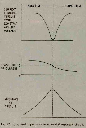
Fig. 61. I_L, I_c, and impedance in a parallel resonant circuit.
The applied voltage was kept constant as the frequency was varied. Since current is minimum through the circuit at resonance, a parallel circuit has a higher impedance at the resonant frequency that at any other.
TIME CONSTANTS
L/R and RC time constants (see Figs. 62 and 63)
indicate how quickly current or voltage builds up when a sudden increase in DC voltage (such as a square wave) is applied to a particular combination of L and R or C and R. One time constant is the time required for voltage (or current, depending on the circuit) to reach 63% of its peak value. The percentage of the peak value can be calculated for any elapsed time if the time constant of the circuit is known. The curves for the voltage increase across a capacitor, or the current increase through an inductor, are exactly the same if the time constants of the two circuits are the same.
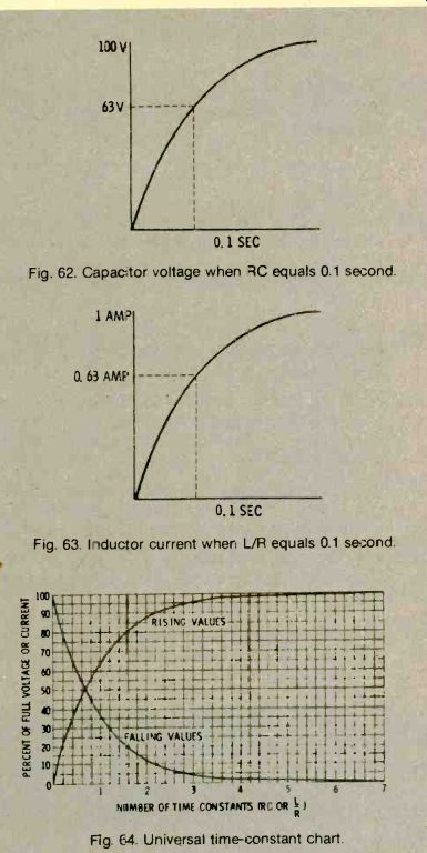
Fig. 62. Capacitor voltage when equals 0.1 second.
Fig. 63. Inductor current when L/R equals 0.1 second.
Fig. 64. Universal time-constant chart.
A universal time-constant chart can be used to calculate the growth and decay of voltage and currents in any RL or RC circuit to which a sudden step voltage is applied. All you have to know is the final voltage and current, and the time constant of ' circuit. See Fig. 64.
Calculate both the voltage across the capacitor and the current in the circuit in the diagram shown in Fig. 65. The time constant is:
RC = 1000 X 0.5 X 10^-6= 0.5 x 10^-3 = 0.5 millisecond
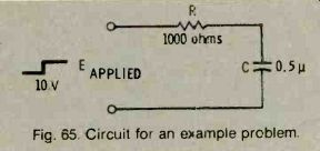
Fig. 65. Circuit for an example problem.
When the 10 Volts is first applied, the current will be E/R = 10,0=0.01 Ampere. Using the time constant and the falling curve in the chart, it can be seen that at the end of one time constant (0.5 millisecond), the current is about 37% of its full value (0.37 X 0.01 = 0.0037 ampere). At the end of two time constants (1 millisecond), current will be 13% (0.13 X 0.01 = 1.3 milli-Amperes). At the end of three time constants, the current will be 5% of its full value (0.05 X 0.01 = 0.5 milli-Ampere), and so on.
The voltage across the capacitor can be determined in a similar manner. When the switch is first closed, Ec is zero. This voltage gradually increases to the value of the power supply, or 10 Volts. At the end of one time constant (0.5 millisecond), Ec will be 63% of maximum (6.3 Volts). At the end of two time constants (1 millisecond), Ec will be 87% of maximum (8.7 volts), etc.
The same chart can be used when the voltage is suddenly removed (the switch is opened). In this case, Ec decays according to the falling curve.
QUESTIONS / ANSWERS
Here are 29 questions and answers on the subject material you have just completed reading. The questions are taken from the original published work, Basic Electricity/Electronics that is described on the first page of this basic course. The questions and answers are only a small portion of the many that interlace the original work where they follow immediately after the subject matter presented. Should you have trouble answering the questions presented here, the Editors suggest that you obtain the original volume, or volumes, and begin a self-teaching program to bolster your basic understanding of AC circuits.
Q1. Voltage and current are always in phase in AC circuits containing only
Q2. An electric heater, an electric iron, and a lamp are fed from the same outlet (connected in parallel). Find the equivalent resistance if you know that the individual resistances are 4 Ohms, 30 Ohms, and 150 Ohms, respectively.
Q3. When current is trying to increase, inductance (makes it increase more quickly; slows down the increase).
Q4. What units are used to measure the inductance of a coil?
Q5. An inductor stores electrical energy by producing a
Q6. Moving a conductor in a magnetic field a current in the conductor.
Q7. How is the inductive reactance of a circuit affected by the input signal?
Q8. If an Ohmmeter is used to measure a coil, it will indicate (DC resistance, inductive reactance). Q9. A filter that allows only high frequencies to pass is called a
Q10. How does a transformer work?
Q11. A "pure" inductance (which has no resistance) would have a (high, low)
Q12. The time constant of a circuit indicates the time it takes a pulse to reach % of its maximum value in that circuit.
Q13. Name two differences between capacitance and inductance.
Q14. Explain what happens when you remove the battery from across a charged capacitor and place a shorting wire across the leads of the capacitor.
Q15. What would happen if you tried to repeat the above experiment without first discharging the capacitor?
Q16. When AC voltage across a capacitor is maximum, the AC current through the circuit is___.
Q17. When an AC current through a capacitor circuit is maximum, the AC voltage across the capacitor is ____.
Q18. If you had two capacitors of low value, how could you combine them to get a larger capacitance?
Q19. How does a mica capacitor differ from an air capacitor of the same physical size?
Q20. How does an increase in the input frequency affect capacitive reactance? Inductive reactance?
Q21. Capacitive impedance is expressed in component form as R-jX. Inductive impedance is expressed as
Q22. How do capacitance and inductance affect a DC input?
Q23. What is the resonant frequency of a circuit containing 2 Henrys in series with 2 pF?
Q24. At what frequency would you measure the Q of a circuit?
Q25. What is the Q of a circuit whose resonant frequency is 1000Hz, inductance is 0.5 Henry, and resistance is 10 Ohms?
Q26. What is the impedance at resonance of a parallel resonant circuit consisting of a 1-Henry inductor with 1 Ohm of DC resistance, and a 1pF capacitor?
Q27. If the resonant frequency of a circuit is 1000 Hz, is 1 Henry, and the Q of the circuit is 80, what is the impedance of the circuit at resonance?
Q28. Is a high or a low power factor desirable in the electrical circuits that are used to transmit the power?
Q29. How can inductive reactance be cancelled in order to increase the power factor in an inductive circuit?
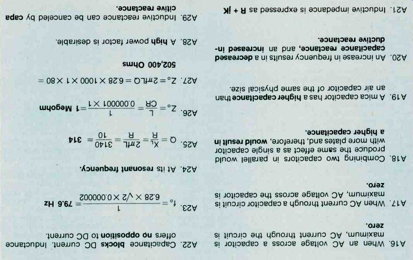
Answers
=======
Also see: Link | --Understanding Electronics